
Method and device for diagnosing pre-charging circuit and power battery system

A technology of pre-charging circuit and diagnostic method, which is applied in the direction of electrical connection testing, etc., can solve the problem that it is difficult to accurately locate the fault location of pre-charging circuit components, and achieve the effect of convenient and timely replacement and maintenance of faulty components

Pending Publication Date: 2022-04-12
章鱼博士智能技术(上海)有限公司
View PDF0 Cites 0 Cited by
  • Summary
  • Abstract
  • Description
  • Claims
  • Application Information

AI Technical Summary

Problems solved by technology

[0005] Embodiments of the present invention provide a diagnostic method, device, and power battery system for a pre-charging circuit to at least solve the technical problem that traditional diagnostic solutions are difficult to accurately locate the fault location of devices in the pre-charging circuit

Method used


Image

  • Method and device for diagnosing pre-charging circuit and power battery system
  • Method and device for diagnosing pre-charging circuit and power battery system
  • Method and device for diagnosing pre-charging circuit and power battery system

Examples


Embodiment 1

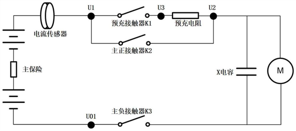
[0026] figure 1 is a schematic diagram of a precharge circuit according to an embodiment of the present invention, such as figure 1As shown, the pre-charging circuit includes battery, current sensor, main positive contactor, main negative contactor, pre-charging contactor, pre-charging resistor, X capacitor, vehicle load and main fuse. The pre-charging circuit has three high-voltage sampling Among them, the first high-voltage sampling point is located on the line between the pre-charging contactor and the positive pole of the battery, the second high-voltage sampling point is located on the line between the pre-charging resistor and the vehicle load, and the third high-voltage sampling point is located on the line between the pre-charging On the line between the charging contactor and the pre-charging resistor.

[0027] It should be noted that, in order to realize the separate diagnosis of the pre-charging contactor and the pre-charging resistor, it is necessary to set the pr...

Embodiment 2

[0061] According to another aspect of the embodiment of the present invention, a diagnostic device for a pre-charging circuit is also provided, the pre-charging circuit includes a battery, a current sensor, a main positive contactor, a main negative contactor, a pre-charging contactor, a pre-charging resistor, X capacitor, vehicle load and main insurance, the pre-charging circuit has three high-voltage sampling points, among which, the first high-voltage sampling point is located on the line between the pre-charging contactor and the positive pole of the battery, and the second high-voltage sampling point is located on the line between the pre-charging contactor and the positive pole of the battery. On the line between the resistor and the vehicle load, the third high-voltage sampling point is located on the line between the pre-charging contactor and the pre-charging resistor. Figure 5 is a schematic diagram of a diagnostic device for a precharge circuit according to an embod...

Embodiment 3

[0073] According to another aspect of the embodiments of the present invention, there is also provided a power battery system, including a memory and a processor, a computer program is stored in the memory, and the processor is configured to execute any one of the above-mentioned precharging circuits through the computer program diagnostic method.


PUM


Abstract

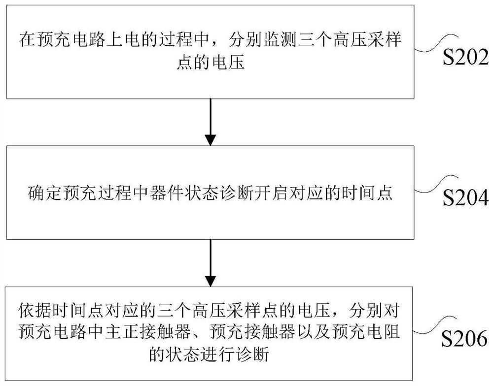
The invention discloses a diagnosis method and device of a pre-charging circuit and a power battery system. The pre-charging circuit comprises a battery, a current sensor, a main positive contactor, a main negative contactor, a pre-charging contactor, a pre-charging resistor, an X capacitor, a whole vehicle load and a main fuse, the pre-charging circuit is provided with three high-voltage sampling points, the first high-voltage sampling point is located on a circuit between the pre-charging contactor and the positive electrode of the battery, and the second high-voltage sampling point is located on a circuit between the pre-charging contactor and the negative electrode of the battery. The first high-voltage sampling point is located on a line between the pre-charging resistor and the whole vehicle load, the second high-voltage sampling point is located on a line between the pre-charging resistor and the whole vehicle load, and the third high-voltage sampling point is located on a line between the pre-charging contactor and the pre-charging resistor. Determining a time point corresponding to starting of device state diagnosis in the pre-charging process; according to the voltages of the three high-voltage sampling points corresponding to the time point, the states of a main positive contactor, a pre-charging contactor and a pre-charging resistor in the pre-charging circuit are diagnosed. According to the invention, the technical problem that the fault position of the device in the pre-charging circuit is not easy to accurately locate by a traditional diagnosis scheme is solved.

Description

technical field [0001] The invention relates to the field of new energy vehicles, in particular to a diagnostic method and device for a precharging circuit and a power battery system. Background technique [0002] Before the power battery of a new energy vehicle is applied to the high voltage, it is necessary to connect the pre-charging circuit first, and charge the X capacitor at the load end of the vehicle through the pre-charging circuit, so as to prevent the high voltage from being directly connected and the X capacitor not being charged, resulting in instantaneous current shock damage to the high-voltage load. . The high-voltage pre-charging circuit mainly includes a pre-charging resistor and a pre-charging contactor. The high-voltage contactor, including the main contactor and the pre-charge contactor, is mainly used to control the on-off of the high-voltage circuit. In order to ensure the normal operation of the high-voltage contactor and avoid high-voltage accidents...

Claims


Application Information

Patent Timeline
IPC IPC(8): G01R31/68
Inventor 李鑫杨红新张建彪仇惠惠史超何强
Owner 章鱼博士智能技术(上海)有限公司
Learn More