Positioning method based on smart LED lamps

A technology of LED smart light and positioning method, applied in the field of measurement, can solve the problems of poor accuracy, high cost, poor anti-interference ability, etc., and achieve the effects of simple structure, low cost and high reliability

Active Publication Date: 2018-05-04
DONGGUAN GUANGJIN PHOTOELECTRIC
View PDF8 Cites 5 Cited by
  • Summary
  • Abstract
  • Description
  • Claims
  • Application Information

AI Technical Summary

Problems solved by technology

[0002] At present, there are two ways to use LED lights for positioning. One is to measure the intensity of light in different places after lighting the LED lights to locate, and the other is to locate by calculating the time difference between emitting and receiving LED light. Both methods have problems of poor anti-interference ability, poor precision and high cost

Method used


Image

  • Positioning method based on smart LED lamps
  • Positioning method based on smart LED lamps
  • Positioning method based on smart LED lamps

Examples


Embodiment approach 1

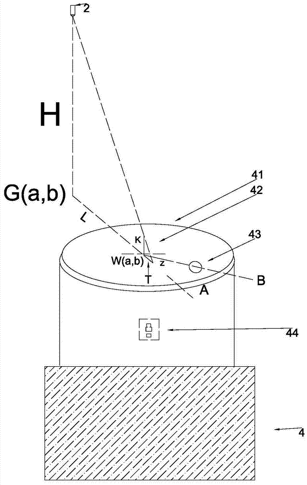
[0026] Implementation Mode 1: Using an LED smart light and an electronic compass for positioning Principle: We first set a coordinate system x, y on the ground as a plane, first set an origin O(0,0) on the ground, and take the true north of the earth as y The positive direction of the axis, and the east direction is the positive direction of the x-axis.

[0027] In addition, we assume that a movable plane disk placed horizontally on the ground is used as the projection disk (assuming that its plane is the same as the ground plane), and the center coordinate of the projection disk is set to W(x, y), and a A standard length projection rod, the height of the projection rod is K, and a line segment WZ is marked on the projection disk with this center point as a reference line for measuring the shadow angle of the projection rod. We know that as the projection disk moves, the shadow length of the projection rod and the angle relative to the line segment WZ will change (such as fig...

Embodiment approach 2

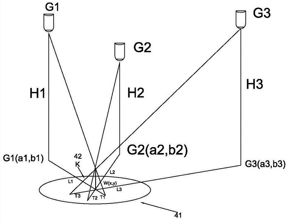
[0046] Embodiment 2 is a three-point positioning method realized by three or more LED smart lights (such as figure 2 )

[0047] The working process and hardware composition of this positioning method are basically similar to those of solution 1, except that the electronic compass is canceled and there is no need to test the shadow angle. In solution 2, at least 3 LED smart lights need to be selected to light up and measure their shadows length, and then determine the coordinate position of the object 4 by calculating with a three-point positioning method. Here, we will focus on describing its principle.

[0048] First, as in Embodiment 1, a coordinate system is set, and there are three LED smart lights 2 (G1, G2, G3) in the upper space near the object 4 to be positioned, and their vertically downward projected coordinates on the ground are G1 (a1, b1), G2(a2,b2), G3(a3,b3); assume that the height of the lamp 2 perpendicular to the ground is H1, H2, H3 respectively; set the c...


PUM


Abstract

The invention discloses a positioning method based on smart LED lamps. According to the method, one or more LED lamps are mounted indoors, a shadow bar with standard length is vertically mounted on anobject to be positioned, a horizontal projection disc is horizontally arranged under the shadow bar, a shadow can be projected on the projection disc by the shadow bar when LED lamps emit light, theposition of the object relative to the LED lamp can be calculated by measuring length and angle of the shadow of the shadow bar under the condition of knowing coordinate position and height of the lamps and height of the shadow bar, and the purpose of positioning is achieved. On the basis of the characteristics of short response time, adjustable drive current and easy modulation of the LED lamps,the LED lamps are respectively and alternately lighted by high-pulse current produced by a control circuit in a short time, and corresponding shadows are measured, so that the problem of ghosting of multiple shadows when the multiple LED lamps are lighted simultaneously can be solved.

Description

technical field [0001] This patent relates to a measurement field, in particular to a positioning method using a lamp. Background technique [0002] At present, there are two ways to use LED lights for positioning. One is to measure the intensity of light in different places after lighting the LED lights to locate, and the other is to locate by calculating the time difference between emitting and receiving LED light. Both methods have the problems of poor anti-interference ability, poor precision and high cost. [0003] Install one or more LED lights in a room, install a standard-length projection pole vertically on the object to be positioned, and install a horizontal projection disc under the projection pole. When the LED lights up, the projection pole will project below it. A shadow of a certain length and angle is projected on the disk, and the length and angle of the shadow are picked up by a camera or a sensor or other device. After the coordinate position, height, an...

Claims


Application Information

Patent Timeline
IPC IPC(8): G01C3/22
CPCG01C3/22
Inventor 周常站
Owner DONGGUAN GUANGJIN PHOTOELECTRIC
Why Eureka
Try Eureka