Oil pipe blanking plug for operation under pressure

A technology of tubing plug and pressure operation, which is applied in wellbore/well components, sealing/package, earthwork drilling and production, etc. It can solve the problems of early setting, poor setting, time-consuming and labor-consuming, etc., to avoid The plug is stuck, the reliability of setting is high, and the effect of ensuring the quality of setting is guaranteed

Active Publication Date: 2022-04-12
SICHUAN SHENGNUO OIL & GAS ENG TECH SERVICE CO LTD +1
View PDF22 Cites 0 Cited by
  • Summary
  • Abstract
  • Description
  • Claims
  • Application Information

AI Technical Summary

Problems solved by technology

In the process of realizing the present invention, the inventors found that there are at least the following problems in the prior art: in the operation under pressure, most of the plugs used are mechanical hands-off plugs, the setting pressure of which is fixed and the change of downhole pressure cannot be monitored. The quality of setting cannot be guaranteed; the plugging is prone to problems such as jamming and early setting during use; Time-consuming and labor-intensive, and there are safety hazards

Method used


Image

  • Oil pipe blanking plug for operation under pressure
  • Oil pipe blanking plug for operation under pressure
  • Oil pipe blanking plug for operation under pressure

Examples


Embodiment 1

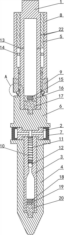
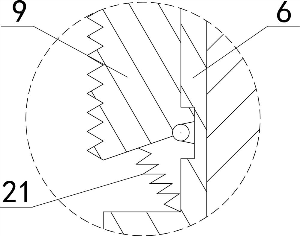
[0028] Such as figure 1 and figure 2 As shown, a oil pipe plug for working under pressure in this embodiment includes a mandrel, a fixed cylinder 5, a transition cylinder 6, a rubber cylinder 7, a working cylinder 8, slips 9, a pump body, a one-way valve and a processor , the mandrel includes an upper joint 1, a connecting block 2, a support block 3 and a lower joint 4, the fixed cylinder 5 is sleeved on the upper part of the upper joint 1, the lower end of the upper joint 1 is connected with the upper end of the transition cylinder 6, and the lower end of the transition cylinder 6 It is connected with the connection block 2, the connection block 2 is connected with the lower joint 4, the support block 3 is set in the lower joint 4, the one-way valve is set in the support block 3, the rubber cartridge 7 is installed on the connection block 2, and the rubber cartridge 7 is subjected to Extrusion of the shoulder of the transition cylinder 6 and the lower joint 4; the connectin...

Embodiment 2

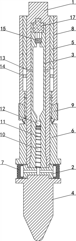
[0038] Such as image 3 As shown, the oil pipe plug for working under pressure in this embodiment is similar in structure to the oil pipe plug in Embodiment 1, the difference is that only one pump body of the oil pipe plug in this embodiment is provided, which is the first pump body 15; the processor is also only provided with one, which is the first processor 17; the mandrel includes an upper joint 1, a connecting block 2, a support block 3 and a lower joint 4, and the upper joint 1 is connected with the upper end of the connecting block 2, and the connecting block 2 The lower end is connected with the lower joint 4, the support block 3 is set in the upper joint 1; the one-way valve is set in the support block 3, the rubber tube 7 is installed on the connection block 2, and the two ends of the connection block 2 are respectively connected with the one-way valve. The small hole that the valve communicates with the rubber cartridge 7. The first pump body 15 is arranged on the ...


PUM


Abstract

The invention belongs to the technical field of oil-gas field development, and discloses a tubing plug for under-pressure operation, which comprises a mandrel, the mandrel is sleeved with a fixed cylinder, a transition cylinder and a rubber cylinder, a working cylinder is slidably sleeved on the fixed cylinder and the transition cylinder, a slip is mounted on the transition cylinder, and the slip abuts against the working cylinder; a pump body and a one-way valve are arranged in the mandrel, the one-way valve is communicated with the rubber barrel, and a through hole is formed in the side wall of the mandrel and communicated with an annular space between the working barrel and the mandrel. According to the tubing plug for under-pressure operation, hydraulic setting is adopted, the pressure is maintained through the one-way valve and the adjusting valve, the influence of the underground environment on the plug is small, and the setting reliability is high; setting pressure can be controlled according to underground pressure, the plugging effect is good, and the device is suitable for high-pressure gas wells. The connection between the underground and the ground is established through microwave communication, and a ground console can control the hydraulic setting of the blanking plug and can also adjust the setting pressure to complete the secondary setting.

Description

technical field [0001] The invention belongs to the technical field of oil and gas field development, and in particular relates to a plugging device for an oil pipe used in pressure operation. Background technique [0002] In the workover process of oil and gas wells, the well killing method was used to avoid blowout in the past, that is, to balance the bottom hole pressure by injecting killing fluid. However, the killing operation will not only pollute the environment, but also the killing fluid will invade the production layer, causing the production layer to be blocked and reducing the oil production. Therefore, the snubbing operation is often used at present. For high-pressure gas wells, snubbing operation can avoid the use of killing fluid, protect the production layer to the maximum extent, and avoid excessive wellhead pressure caused by rising and accumulating gas at the bottom of the well, greatly reducing the risk of gas well blowout and improving the production eff...

Claims


Application Information

Patent Timeline
Patent Type & Authority Applications(China)
IPC IPC(8): E21B33/12
Inventor 周长林范宇罗伟董亮亮冯星铮贾沙沙黄利刘晓东刘睿陈刚何亚锐
Owner SICHUAN SHENGNUO OIL & GAS ENG TECH SERVICE CO LTD
Why Eureka
Try Eureka