Automatic flame-retardant device for safety door based on temperature-sensitive glass control
A safety door and glass door technology, applied in the field of intelligent equipment, can solve the problems of poor flame retardant performance of the safety door, damage to the safety door, broken glass, etc., and achieve the effect of increasing the flame retardant effect, improving the service life, and increasing the protective function.
- Summary
- Abstract
- Description
- Claims
- Application Information
AI Technical Summary
Problems solved by technology
Method used
Image
Examples
Embodiment 1
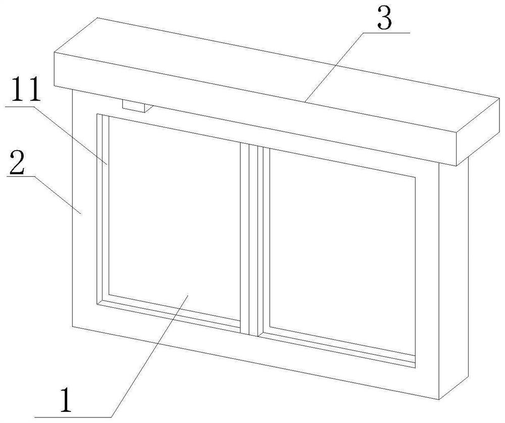
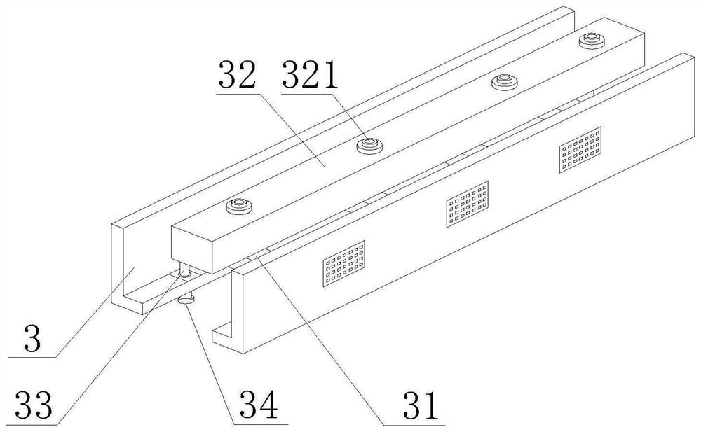
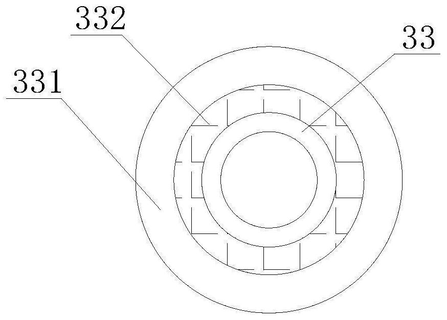
[0045] Such as Figure 1-8 As shown, the present invention provides an automatic flame retardant device for safety doors based on temperature-sensitive glass control, which includes a glass door main body 1, a door frame 2 and a protective baffle 3, and a sealing block 11 is fixedly installed on the outer side of the glass door main body 1, and the sealing block 11 A door frame 2 is fixedly installed on the outside of the door frame 2, and a protective baffle 3 is fixedly installed on the top of the door frame 2. A fire alarm is installed on one side of the bottom of the protective baffle 3. A flame-retardant mechanism is installed inside the protective baffle 3. The inside of the door frame 2 An anti-collision mechanism is provided, and the flame retardant mechanism includes a fixed plate 31, the two ends of the fixed plate 31 are fixedly installed inside the protective baffle 3, the top of the fixed plate 31 is fixedly installed with a storage box 32, and one side of the stor...
Embodiment 2
[0048] Such as Figure 1-8 As shown, on the basis of Embodiment 1, the present invention provides a technical solution: preferably, the anti-collision mechanism includes a limiting plate 23, the inner side of the limiting plate 23 is fixedly equipped with a buffer column 231, and the side of the buffer column 231 is fixed Anti-collision plate 24 is installed, and the bottom of anti-collision plate 24 is provided with telescopic column 241, and the both sides of telescopic column 241 is provided with folding bar 242, and the bottom of folding bar 242 is provided with fixed base 243, and the side of folding bar 242 is provided with cushioning Pressure column 2421, the outer side of buffer pressure column 2421 is provided with rebound column, the bottom of buffer pressure column 2421 is arranged on the top of fixed base 243, the inside of anti-collision plate 24 is provided with mobile column 2423, and the both sides of mobile column 2423 are provided with Squeeze the spring post...
Embodiment 3
[0051] Such as Figure 1-8 As shown, on the basis of Embodiment 1, the present invention provides a technical solution: preferably, a reinforcement plate 2221 is provided on the outside of the limiting column 222, and a support plate 2222 is fixedly installed on the inside of the reinforcement plate 2221, and the reinforcement plate 2221 A connecting ring 2225 is fixedly installed inside, a reinforcing bar 2223 is arranged on the top of the reinforcing plate 2221, a reinforcing block 2224 is fixedly installed on the top of the reinforcing bar 2223, and a shock absorbing pad 2226 is arranged on the inner side of the reinforcing block 2224, and the inner side of the shock absorbing pad 2226 is fixed Mounting pads 2227 are installed.
[0052] In this embodiment, through the mutual cooperation of the reinforcement plate 2221 and the support plate 2222, the fixity of the reinforcement plate 2221 is used to increase the reinforcement performance of the limit column 222, and at the s...
PUM
 Abstract
Description
Claims
Application Information
 - R&D
- Intellectual Property
- Life Sciences
- Materials
- Tech Scout
- Unparalleled Data Quality
- Higher Quality Content
- 60% Fewer Hallucinations
Browse by: Latest US Patents, China's latest patents, Technical Efficacy Thesaurus, Application Domain, Technology Topic, Popular Technical Reports.
© 2025 PatSnap. All rights reserved.Legal|Privacy policy|Modern Slavery Act Transparency Statement|Sitemap|About US| Contact US: help@patsnap.com


