Wire feeder for welding equipment
A technology of welding equipment and wire feeder, applied in welding equipment, arc welding equipment, welding accessories, etc., can solve the problems of poor stability of wire feeder, welding failure, affecting welding quality, etc., to increase the fixed function and convenience. The effect of adjusting the position and increasing the protective performance
- Summary
- Abstract
- Description
- Claims
- Application Information
AI Technical Summary
Problems solved by technology
Method used
Image

Examples
Embodiment 1
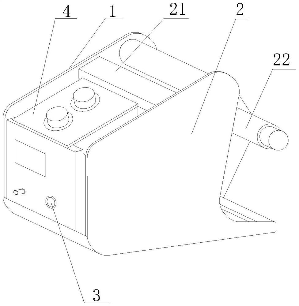
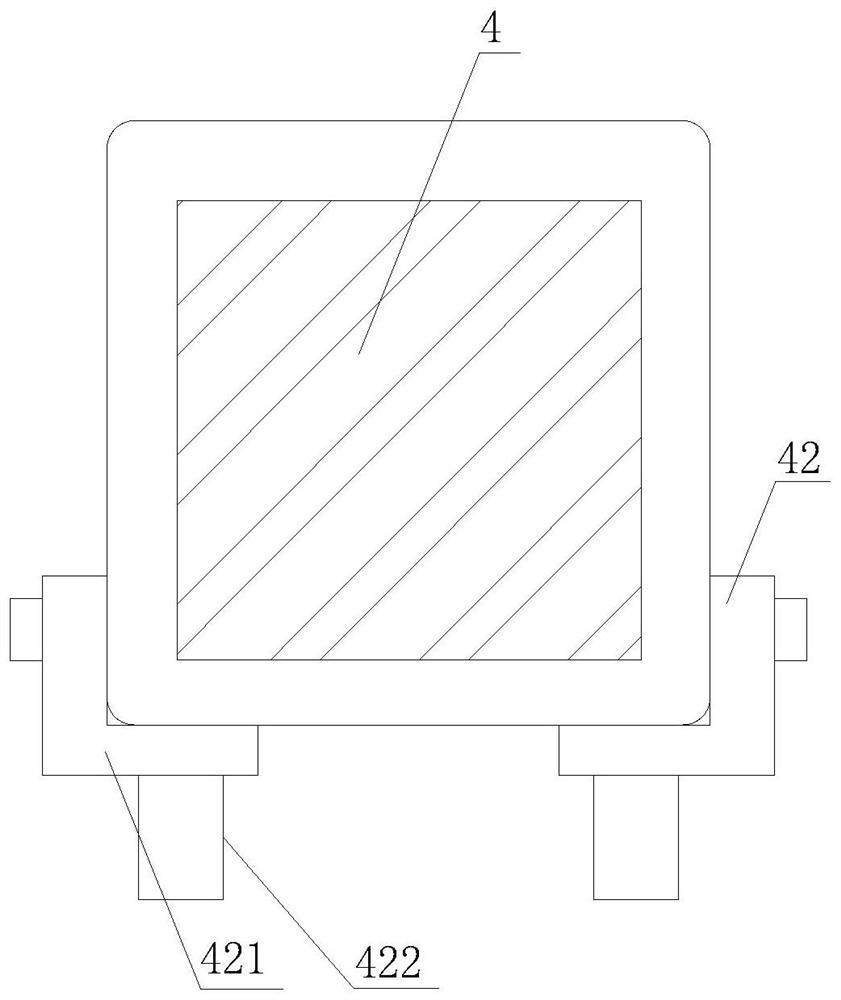
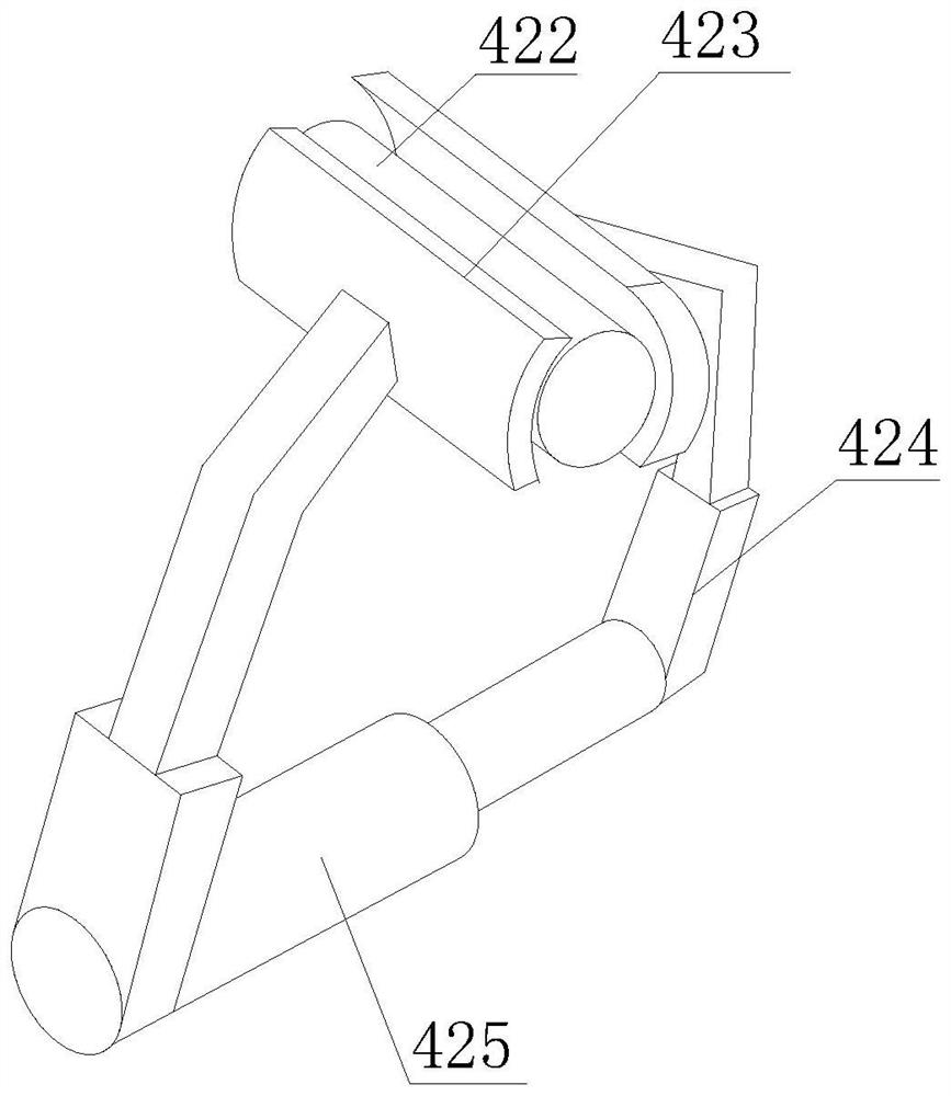
[0043] Such as Figure 1-7 As shown, the present invention provides a wire feeder for welding equipment, including a wire feeder main body 1, a housing 2, a control panel 3 and a wire feeding power mechanism 4, and the outer side of the wire feeding device main body 1 is fixedly installed with a housing 2 , the inside of the shell 2 is fixedly installed with a wire feeding power mechanism 4, the top of the wire feeding power mechanism 4 is fixedly installed with a connecting column 21, the side of the wire feeding power mechanism 4 is fixedly installed with a control panel 3, and the bottom of the wire feeding power mechanism 4 is fixed A stabilizing mechanism 41 is installed, and a wire feeding column 22 is movably installed on one side inside the shell 2, and an adjusting mechanism 23 is arranged on the side of the wire feeding column 22, and the stabilizing mechanism 41 includes a fixing mechanism 42, and a fixing block is fixedly installed on the side of the fixing mechanis...
Embodiment 2
[0046] Such as Figure 1-7 As shown, on the basis of Embodiment 1, the present invention provides a technical solution: preferably, the bottom of the fixing mechanism 42 is fixedly installed with a shock absorbing mechanism 43, and the top of the shock absorbing mechanism 43 is fixedly installed with a shock absorbing pad 431, and the top of the shock absorbing pad 431 A pressing block 4311 is fixedly installed, the bottom of the pressing block 4311 is fixedly equipped with an airbag block 4312, both sides of the bottom of the airbag block 4312 are fixedly installed with a pressing elastic block 4313, and the bottom of the pressing elastic block 4313 is fixedly installed with a positioning block 4314 and a shock absorber Both sides of the bottom of 431 are movable with pressing rod 4321, and the inner side of pressing rod 4321 is fixedly installed with extrusion spring 4322, and the side of pressing rod 4321 is movably connected with No. 1 magnetic block 4323, and No. 1 magneti...
Embodiment 3
[0049] Such as Figure 1-7 As shown, on the basis of Embodiment 1, the present invention provides a technical solution: preferably, the adjustment mechanism 23 includes a moving groove 231, and a moving block 232 is movably installed inside the moving groove 231, and a moving block 232 is fixedly installed on the side of the moving block 232. The connecting block, the other side of the connecting block is fixedly installed on the side of the wire feeding column 22, the side of the moving block 232 away from the wire feeding column 22 is fixedly installed with a speed change block 233, and the side of the speed change block 233 is fixedly installed with a power motor 234, moving One side and the bottom of the groove 231 are fixedly equipped with a moving strip 235 , and the side of the moving strip 235 is movably installed on the side of the moving block 232 .
[0050] In this embodiment, the control panel 3 is used to adjust, so that the power motor 234 drives the moving block...
PUM
 Abstract
Description
Claims
Application Information
 - R&D
- Intellectual Property
- Life Sciences
- Materials
- Tech Scout
- Unparalleled Data Quality
- Higher Quality Content
- 60% Fewer Hallucinations
Browse by: Latest US Patents, China's latest patents, Technical Efficacy Thesaurus, Application Domain, Technology Topic, Popular Technical Reports.
© 2025 PatSnap. All rights reserved.Legal|Privacy policy|Modern Slavery Act Transparency Statement|Sitemap|About US| Contact US: help@patsnap.com