
Propeller speed regulator

A technology for propellers and governors, applied in propellers, aircraft parts, transportation and packaging, etc., can solve problems such as waste, easy damage to the engine, and difficulty in ensuring oil circuit sealing.

Pending Publication Date: 2021-03-26
AVIC HUIYANG AVIATION PROPELLER
View PDF0 Cites 0 Cited by
  • Summary
  • Abstract
  • Description
  • Claims
  • Application Information

AI Technical Summary

Problems solved by technology

However, the existing propeller speed governors balance the centrifugal force of the counterweight and the spring force to maintain the constant balanced speed of the propeller. There is only one balanced speed, which is the same speed during take-off and cruise level flight, which cannot be selected, which leads to In the case that the take-off task can be completed, if the balance speed is set higher, the take-off task can be completed more smoothly and efficiently, and the engine is not easy to be damaged, but a lot of fuel is wasted during cruising and level flight, and the fuel consumption is very high. If The lower the balance speed is set, the fuel is saved during cruising and level flight, but although the aircraft completes the take-off task, it needs a large amount of fuel to burn to generate greater power, so it not only wastes fuel, but also easily damages the engine; so according to the aircraft However, in any case, as long as the balance speed can meet the take-off requirements, a lot of fuel will be wasted during cruising and level flight, so it is urgent to study an optional speed that can realize adjustable balance speed. Controlled propeller governor to ensure that the thrust of the propeller is large when the aircraft takes off, and the thrust of the propeller is small when the aircraft is cruising and flying
The flight of the aircraft is guaranteed by the adjustment of the speed of the propeller and the blade angle. The propeller only has one high-efficiency blade angle. In order to keep the rotational speed constant under certain conditions, it is necessary to change the blade angle to absorb the engine power, which makes the working efficiency of the propeller low. In order to maintain the working efficiency of the propeller at a high efficiency, it is also urgent to study an alternative Adjustable and controllable propeller governor, which can achieve balanced speed, so that the blade angle can always be kept at the position of high-efficiency blade angle
Moreover, the existing propeller governor does not have a small-pitch limiting mechanism, and the propeller uses an end-face tooth meshing mechanism for fixed-distance protection. The end-face tooth meshing mechanism has a complex structure, which increases the volume and weight of the propeller, and can no longer meet the needs of some aircraft such as airplanes. According to the application requirements, it is also urgent to study a propeller governor with the function of small-pitch limiting and fixed-pitch protection.
In addition, the feathering function of the existing propeller is realized by switching the oil circuit governor and the oil circuit in the propeller. There are many oil circuits in the governor and the propeller. The structure of the oil circuit is very complicated, and it is not easy to manufacture. , and it is not easy to ensure the sealing of each oil circuit; the existing governor does not have the function of β control and anti-propeller, and the aircraft lands and taxis by reducing the propeller blade angle within a certain range to achieve a certain damping effect, but the effect is minimal , the taxiing distance of the aircraft landing is long, and a very long runway needs to be set up, which wastes land resources and reduces the utilization rate of existing land resources

Method used


Image

  • Propeller speed regulator
  • Propeller speed regulator
  • Propeller speed regulator

Examples


Embodiment Construction

[0049] The present invention will be further described below in conjunction with the accompanying drawings and specific embodiments.

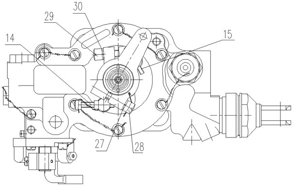
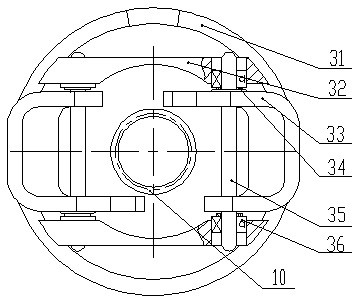
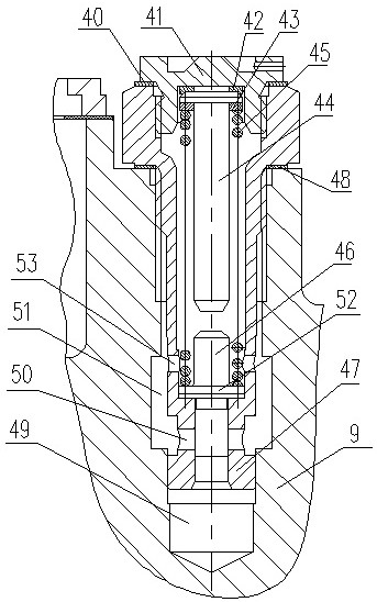
[0050] Such as Figure 1 to Figure 16 As shown, this embodiment includes an upper housing assembly 1, a lower housing assembly 9, a base plate 16, an oil filter assembly, and a speed selection device installed in the upper and lower housing assemblies 1, 9, the base plate 16, and the inner hole of the oil filter assembly. Mechanism, the power turbine adjustment assembly installed in the upper casing assembly 1, the gear pump 97 installed in the lower casing assembly 9, the pressure regulating valve assembly 96, the beta valve assembly 69 and the reset handle assembly 70 connected to the power push-pull rod. The upper housing assembly 1 is sealed and fixed on the upper end surface of the lower housing assembly 9 by a sealing pad. The lower housing assembly 9 is sealed and fixed on the upper end surface of the bottom plate 16 by a sealing ring. ...


PUM


Abstract

The invention discloses a propeller speed regulator which comprises an upper shell assembly, a lower shell assembly, a bottom plate, an oil filter assembly, a speed selecting mechanism, a power turbine adjusting assembly, a gear pump, a pressure regulating and beta valve assembly and a reset handle assembly. Engine incoming oil is connected with a low-pressure oil groove in a bottom plate throughan oil filter assembly, and a gear pump outlet is divided into two paths which are connected with a high-pressure oil inlet of a beta valve assembly and a high-pressure oil cavity of a safety valve assembly respectively. A low-pressure oil cavity of the safety valve assembly is connected with a low-pressure oil groove; a high-pressure oil outlet of the beta valve assembly is connected with a high-pressure oil inlet of the speed selecting mechanism, and a high-pressure oil outlet of the speed selecting mechanism is connected with a propeller oil cavity; an oil return cavity of the beta valve assembly is connected with an oil groove II of the speed selecting mechanism; an oil return port of the speed selecting mechanism is connected with an oil return groove of the engine. The speed governorhas the advantages that the speed can be selected, feathering can be controlled, reverse propeller and balance rotating speed can be adjusted and controlled, the propeller using the speed governor ishigh in working efficiency, a large amount of fuel oil is saved, and working safety and reliability are high.

Description

technical field [0001] The invention relates to a propeller governor. Background technique [0002] The higher the rotation speed of the propeller, the greater the thrust generated, and the thrust required by the aircraft to take off is large, and the thrust required by the aircraft to cruise and level flight is small. However, the existing propeller speed governors balance the centrifugal force of the counterweight and the spring force to maintain the constant balanced speed of the propeller. There is only one balanced speed, which is the same speed during take-off and cruise level flight, which cannot be selected, which leads to In the case that the take-off task can be completed, if the balance speed is set higher, the take-off task can be completed more smoothly and efficiently, and the engine is not easy to be damaged, but a lot of fuel is wasted during cruising and level flight, and the fuel consumption is very high. If The lower the balance speed is set, the fuel is ...

Claims


Application Information

Patent Timeline
IPC IPC(8): B64C11/30B64C11/38
CPCB64C11/303B64C11/38
Inventor 徐丁丁郝丽陈双双张鹤方王春慧
Owner AVIC HUIYANG AVIATION PROPELLER
Learn More