Feeding system for continuous pipe tunnel pyrolyzing furnace

A technology of feeding system and pyrolysis furnace is applied in the field of feeding system of continuous tube-tunnel pyrolysis furnace, which can solve the problems of wasting resources, increasing disposal costs, potential safety hazards, etc. material, ensure the effect of safety

Pending Publication Date: 2022-04-12
黑龙江九地生金科技有限公司
View PDF0 Cites 0 Cited by
  • Summary
  • Abstract
  • Description
  • Claims
  • Application Information

AI Technical Summary

Problems solved by technology

[0003] The applicant found that there are at least the following technical problems in the prior art: the feeding system first needs to ensure the uninterrupted continuous operation of the tube tunnel furnace. If it is smaller than the disposal capacity of the tube-tunnel furnace, resources will be wasted, disposal costs will be increased, and uniform feeding cannot be maintained, which will also cause fluctuations in disposal results
In addition, it is unavoidable to mix and bring in some air during the feeding process. Since the volatile hydrocarbons produced by oily sludge are mixed with air at high temperatures, they are very likely to form explosive gases, which is likely to bring greater safety hazards.

Method used


Image

  • Feeding system for continuous pipe tunnel pyrolyzing furnace
  • Feeding system for continuous pipe tunnel pyrolyzing furnace

Examples


Embodiment 1

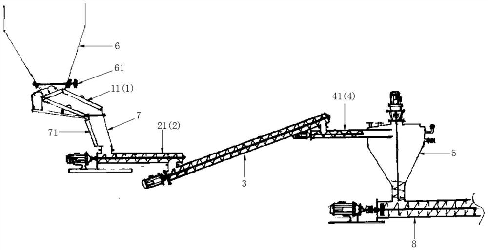
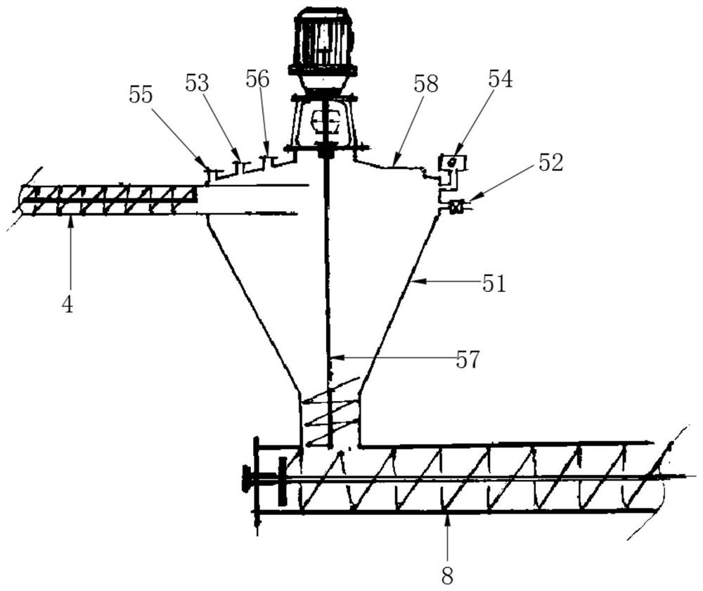
[0034] refer to Figure 1 to Figure 2 , the present invention mentions a feed system for a continuous pipe tunnel pyrolysis furnace, including a feeding assembly 1, a metering assembly 2, an intermediate conveyor 3, an extrusion assembly 4, and a nitrogen-filled silo 5, and a hopper 6 The bottom is connected with the feeding end of the feeding assembly 1, and the discharging end of the feeding assembly 1 is connected with the feeding end of the metering assembly 2 through the pipeline 7, and the feeding assembly 1 is connected with the metering assembly 2 in communication, and the metering assembly 2 The discharge end is connected to the feed end of the intermediate conveyor 3, the discharge end of the intermediate conveyor 3 is connected to the feed end of the extrusion assembly 4, and the discharge end of the extrusion assembly 4 is connected to the nitrogen-filled silo 5 Through, the bottom of the nitrogen-filled feed bin 5 communicates with the tube tunnel furnace 8;

[0...

Embodiment 2

[0038] refer to Figure 1 to Figure 2 , the present invention mentions a feed system for a continuous pipe tunnel pyrolysis furnace, including a feeding assembly 1, a metering assembly 2, an intermediate conveyor 3, an extrusion assembly 4, and a nitrogen-filled silo 5, and a hopper 6 The bottom is connected with the feeding end of the feeding assembly 1, and the discharging end of the feeding assembly 1 is connected with the feeding end of the metering assembly 2 through the pipeline 7, and the feeding assembly 1 is connected with the metering assembly 2 in communication, and the metering assembly 2 The discharge end is connected to the feed end of the intermediate conveyor 3, the discharge end of the intermediate conveyor 3 is connected to the feed end of the extrusion assembly 4, and the discharge end of the extrusion assembly 4 is connected to the nitrogen-filled silo 5 Through, the bottom of the nitrogen-filled feed bin 5 communicates with the tube tunnel furnace 8;

[0...


PUM


Abstract

The invention provides a feeding system for a continuous pipe tunnel pyrolyzing furnace, and relates to the technical field of pipe tunnel furnaces. The device comprises a feeding assembly, a metering assembly, an intermediate conveyor, an extrusion assembly and a nitrogen charging bin, a hopper is communicated with the feeding assembly, the feeding assembly is communicated with the metering assembly through a pipeline, the feeding assembly is in communication connection with the metering assembly, the metering assembly is communicated with the intermediate conveyor, the intermediate conveyor is communicated with the extrusion assembly, and the extrusion assembly is communicated with the nitrogen charging bin. The extrusion assembly is communicated with the nitrogen charging bin, the nitrogen charging bin is communicated with the pipe tunnel furnace, the feeding assembly and the metering assembly are arranged and are in communication connection, the metering assembly can continuously control and automatically adjust the feeding assembly through electric signals to achieve the preset feeding amount, constant-speed feeding is achieved, and uninterrupted continuous operation of the pipe tunnel furnace is guaranteed; by arranging the extrusion assembly and the nitrogen charging bin, air can be effectively isolated, nitrogen charging protection is achieved, meanwhile, gas circulates in a closed state, secondary pollution is avoided, and safety is ensured.

Description

technical field [0001] The invention relates to the technical field of tube tunnel furnaces, in particular to a feed system for continuous tube tunnel pyrolysis furnaces. Background technique [0002] In the process of pyrolyzing oilfield oil sludge with a continuous tube-tunnel furnace, it is necessary to ensure the safe, stable and continuous operation of the tube-tunnel furnace to achieve the ultimate disposal purpose. The ultimate disposal means that the disposal result meets the standard, that is, the solid sludge after the oily sludge is disposed of The oil content is less than 0.3%. The key technical point of the continuous tube tunnel furnace here is the feeding system. [0003] The applicant found that there are at least the following technical problems in the prior art: the feeding system first needs to ensure the uninterrupted continuous operation of the tube tunnel furnace. If it is smaller than the disposal capacity of the tube tunnel furnace, resources will be...

Claims


Application Information

Patent Timeline
Patent Type & Authority Applications(China)
IPC IPC(8): C10B55/02C10B57/00
Inventor 周一新赵磊
Owner 黑龙江九地生金科技有限公司
Why Eureka
Try Eureka