Demoulding mechanism for engine cylinder cover plate

A technology of engine cylinder head and demoulding mechanism, which is applied to household components, household appliances, and other household appliances, and can solve problems such as high cost, complex structure, and large space occupation

Pending Publication Date: 2022-04-12
NINGBO FANGZHENG TOOL
View PDF4 Cites 1 Cited by
  • Summary
  • Abstract
  • Description
  • Claims
  • Application Information

AI Technical Summary

Problems solved by technology

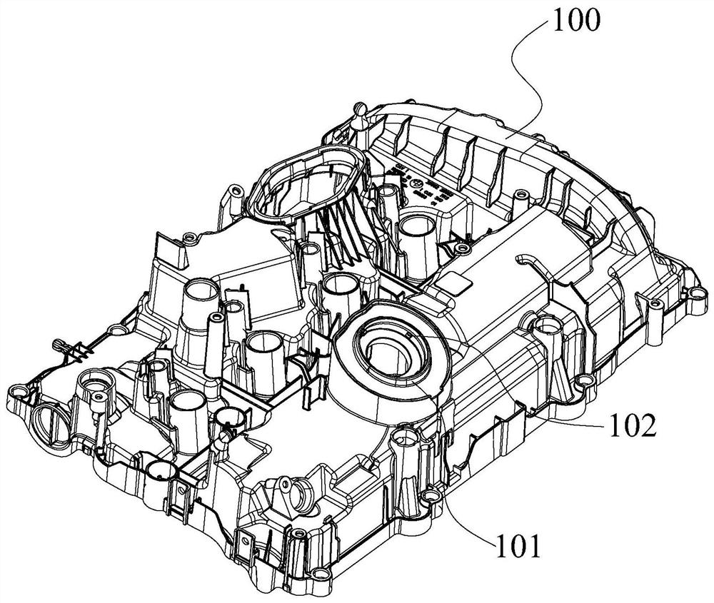
like figure 1 As shown, it is an engine cylinder head plate 100 in the prior art. The upper end of the engine cylinder head plate 100 needs to be formed with an oblique sleeve 101 with an inclined end, and there is an outer wall on the inner side wall of the oblique sleeve 101. The convex undercut 102 structure is precisely due to the existence of the inclined sleeve 101 and the undercut 102 structure. Before the product is opened, it needs to be demolded in advance. The demoulding of this type of structure in the existing mold structure Mechanism design is usually designed as a plurality of mutually independent core-pulling mechanisms to perform core-pulling and demoulding actions respectively, which has a complex structure, takes up a lot of space, and costs high

Method used


Image

  • Demoulding mechanism for engine cylinder cover plate
  • Demoulding mechanism for engine cylinder cover plate
  • Demoulding mechanism for engine cylinder cover plate

Examples


Embodiment Construction

[0026] In order to make the above objects, features and advantages of the present invention more comprehensible, specific embodiments of the present invention will be described in detail below in conjunction with the accompanying drawings.

[0027] In the description of the present invention, it should be noted that the orientation or positional relationship indicated by the terms "upper end", "lower end", "inner, outer", "outer side wall", "inner wall" etc. are based on the orientation or positional relationship shown in the drawings. The positional relationship is only for the convenience of describing the present invention and simplifying the description, but does not indicate or imply that the referred device or element must have a specific orientation, be constructed and operated in a specific orientation, and thus should not be construed as limiting the present invention. In addition, in the description of the present invention, the terms "first" and "second" are only for...


PUM


Abstract

The invention provides an engine cylinder cover plate demolding mechanism which comprises a mold frame, a sliding block, an inclined drawing rod and a driving cylinder are arranged on the mold frame, the sliding block is in sliding fit with the mold frame, and the sliding block is in linkage fit with the inclined drawing rod. The sliding block drives the first core pulling block on the inclined pulling rod to be demolded and separated from the inner wall of an outwards-protruding inclined sleeve on the engine steel cover plate; and an inclined pulling assembly is arranged on the inclined pulling rod in a sliding mode, a second core pulling block is arranged on the inclined pulling assembly, and when the inclined pulling rod slides in a core pulling mode in the direction away from the inclined sleeve, the inclined pulling assembly moves inwards in the radial direction of the inclined pulling rod, so that demolding separation of the second core pulling block and an inverted buckle on the inner wall of the inclined sleeve is achieved. The engine cylinder cover plate demolding mechanism is simple in structure, and inclined hole demolding and inverted buckle demolding of the inner wall of an inclined hole can be conducted at the same time through one driving structure.

Description

technical field [0001] The invention relates to the technical field of injection molds, in particular to a demoulding mechanism for an engine cylinder cover plate. Background technique [0002] At present, with the rapid development of the plastics industry and the continuous improvement of the strength and precision of general and engineering plastics, the application range of plastic products is also expanding, such as: household appliances, instruments, construction equipment, automobile industry and daily use Hardware and many other fields. [0003] In the injection molding process of the product, due to the characteristics of the product's own structure, it is necessary to add a corresponding core-pulling and demoulding mechanism to the mold structure. Only after pre-core-pulling and demoulding some undercut mechanisms on the product can the final mold opening be guaranteed. , to eject the product. Such as figure 1 As shown, it is an engine cylinder head plate 100 in...

Claims


Application Information

Patent Timeline
IPC IPC(8): B29C45/44B29C45/33B29L31/00
Inventor 童嘉鑫严碧勤薛海啸张鹏吴贤益张海豪应镇武黄志高周华民
Owner NINGBO FANGZHENG TOOL
Why Eureka
Try Eureka