Riveting machine and using method thereof

A riveting machine and riveting technology, applied in the directions of feeding device, positioning device, storage device, etc., can solve the problems of low work efficiency, easy occurrence of safety accidents, backward riveting equipment, etc., so as to improve safety and improve the efficiency of riveting processing. Effect

Pending Publication Date: 2022-04-12
中山市美格电子科技有限公司
View PDF0 Cites 1 Cited by
  • Summary
  • Abstract
  • Description
  • Claims
  • Application Information

AI Technical Summary

Problems solved by technology

[0003] In the existing technology, the riveting equipment is relatively backward and has a single function. The processes of stripping, conveying, and feeding all need to be completed manually by operators. There are many disadvantages in actual production: 1) Relying on manual stripping, conveying, and feeding Low efficiency; 2) Human hands operate back and forth in the mold, which has great safety hazards and is prone to safety accidents; 3) Only a single riveting process can be completed each time the mold is closed, and continuous production cannot be realized

Method used


Image

  • Riveting machine and using method thereof
  • Riveting machine and using method thereof
  • Riveting machine and using method thereof

Examples


Embodiment Construction

[0033] The following will clearly and completely describe the technical solutions in the embodiments of the present invention with reference to the accompanying drawings in the embodiments of the present invention. Obviously, the described embodiments are only some, not all, embodiments of the present invention. Based on the embodiments of the present invention, all other embodiments obtained by persons of ordinary skill in the art without making creative efforts belong to the protection scope of the present invention.

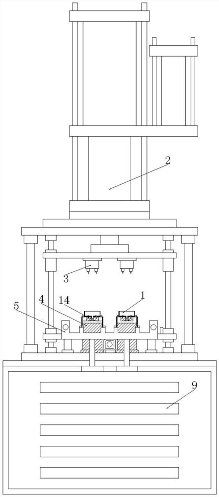
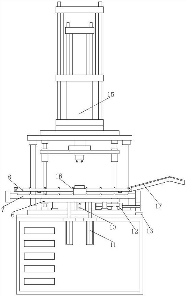
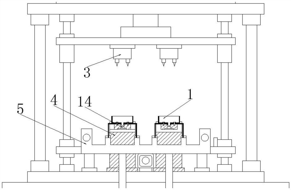
[0034] refer to Figures 1 to 3 , an embodiment provided by the present invention: a riveting machine, including a riveting device 2 for riveting a workpiece 1, the riveting device 2 includes a riveting base 4 and a riveting punch 3 corresponding to the riveting base 4, and also includes a pair of The feeding device 5 that the workpiece 1 moves, the feeding device 5 includes a bracket 8 that is located on the riveting base 4 and places the workpiece 1, a lifti...


PUM


Abstract

The invention discloses a riveting machine which comprises a riveting device for riveting a workpiece, the riveting device comprises a riveting base and a riveting punch corresponding to the riveting base, and the riveting machine further comprises a feeding device for moving the workpiece. The feeding device comprises a bracket which is arranged on the riveting base and used for containing workpieces, a lifting device which ascends and descends relative to the bracket, and a conveying frame which is arranged on the lifting device and used for lifting, conveying and containing the workpieces in the ascending and descending processes of the lifting device. By means of the feeding device, automatic control over stripping, conveying and feeding is achieved, and therefore manual operation is replaced. By means of the feeding device, the riveting finished product workpiece can be separated from the riveting base, the multiple workpieces are synchronously conveyed, the workpiece to be riveted is placed on the riveting base, in the continuous production process, an operator only needs to place the workpiece to be riveted on the feeding side and take out the riveting finished product workpiece on the discharging side, and the riveting machining efficiency is greatly improved.

Description

technical field [0001] The invention relates to the technical field of riveting equipment, in particular to a riveting machine and a use method thereof. Background technique [0002] In the production process, most products need to use riveting processing technology. Take the filter box as an example: workpieces A and B have corresponding riveting holes, and the riveting hole of workpiece A is provided with a flanging structure for workpiece B to be inserted into and assembled . The workpieces A and B are assembled for preliminary positioning, and are manually placed on the riveting base, and the riveting punch and the riveting base form a mold. Start the pressure device to push the riveting punch, and the riveting punch presses into the flanging structure of workpiece A. After the flanging structure is squeezed, it turns to the outside and clamps workpiece B, so as to complete the riveting work of workpieces A and B, and take it out manually Finished product on riveted ba...

Claims


Application Information

Patent Timeline
Patent Type & Authority Applications(China)
IPC IPC(8): B21D39/00B21C51/00B21D43/02B21D45/00
Inventor 殷国辉
Owner 中山市美格电子科技有限公司
Why Eureka
Try Eureka