Inertial sensor correction verification method based on finite element analysis model

An inertial sensor and analysis model technology, applied in the field of inertial sensors, can solve the problems of insufficient accuracy of inertial sensors and unsatisfactory LPF performance, and achieve the effect of reducing electrostatic force requirements and reducing electrostatic force.

Pending Publication Date: 2022-04-08
CHINA UNIV OF GEOSCIENCES (WUHAN)
View PDF0 Cites 0 Cited by
  • Summary
  • Abstract
  • Description
  • Claims
  • Application Information

AI Technical Summary

Problems solved by technology

After the launch of the LPF in 2016, the data obtained show that the accuracy requirements for detecting gravitational waves have been met in the high-frequency region, but at low frequencies, due to the greater influence of Brownian noise, the performance of the LPF cannot meet the requirements for detecting gravitational wave signals. demand, what the present invention will solve is exactly the problem that the inertial sensor of LPF has insufficient precision in the low frequency part

Method used


Image

  • Inertial sensor correction verification method based on finite element analysis model
  • Inertial sensor correction verification method based on finite element analysis model
  • Inertial sensor correction verification method based on finite element analysis model

Examples


Embodiment Construction

[0034] In order to have a clearer understanding of the technical features, purposes and effects of the present invention, the specific implementation manners of the present invention will now be described in detail with reference to the accompanying drawings.

[0035] Embodiments of the present invention provide a verification method, device and storage device for inertial sensor correction based on a finite element analysis model. The size of the existing inertial sensor is 46mm*46mm*46mm, and the finite element analysis method is to simulate the modified electrostatic model of the improved inertial sensor with finite element simulation software.

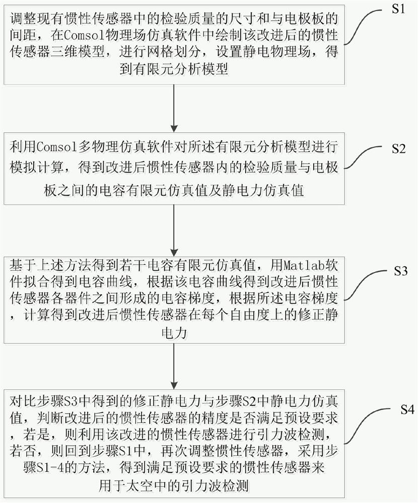
[0036] Please refer to figure 1 , figure 1 It is a flowchart of a verification method for inertial sensor correction based on a finite element analysis model in an embodiment of the present invention, specifically including the following steps:

[0037] S1: Adjust the size of the inspection mass in the existing inertial sensor an...


PUM


Abstract

The invention provides an inertial sensor correction verification method based on a finite element analysis model, and the method comprises the steps: adjusting the size of an inspection mass in an existing inertial sensor and the distance between the inspection mass and an electrode plate, and obtaining an improved inertial sensor; utilizing a finite element analysis model to obtain a capacitance finite element simulation value and an electrostatic force simulation value between the inspection mass and the electrode plate in the improved inertial sensor, and a capacitance gradient formed among devices of the improved inertial sensor; obtaining a corrected electrostatic force according to the capacitance gradient; therefore, the inertial sensor meeting the preset requirements is obtained and is used for gravitational wave detection in the space. The method has the beneficial effects that the electrostatic force borne by the inspection mass in the improved inertial sensor is reduced, and the electrostatic force requirement applied to inertial sensor position control through the injection electrode is reduced.

Description

technical field [0001] The invention relates to the field of inertial sensors, in particular to a verification method for inertial sensor correction based on a finite element analysis model. Background technique [0002] The general theory of relativity is one of the most brilliant achievements of human beings in the field of natural science in the 20th century, and gravitational waves are the most important prediction of general relativity, so the detection of gravitational waves is of great scientific significance to the development of physics. Since LIGO first detected gravitational waves in 2016, dozens of gravitational wave events have been detected by ground-based gravitational wave detection equipment. However, due to the influence of ground vibration noise and ambient temperature, ground detection equipment cannot complete the detection of low-frequency gravitational waves below 1.0 Hz. Gravitational wave detectors in space can greatly reduce these effects, so they ...

Claims


Application Information

Patent Timeline
Patent Type & Authority Applications(China)
IPC IPC(8): G06F30/23G06F119/14
Inventor 吴晗升柯俊
Owner CHINA UNIV OF GEOSCIENCES (WUHAN)
Why Eureka
Try Eureka