
Sound reflection top cover structure for ultrasonic cleaning device

A technology of ultrasonic cleaning and sound reflection, applied in cleaning methods and utensils, cleaning methods using liquids, chemical instruments and methods, etc., can solve problems such as sound energy dissipation, increase sound field intensity, strengthen ultrasonic diffuse reflection, uniformity Effect of cleaning effect

Pending Publication Date: 2022-04-08
NANJING UNIV OF AERONAUTICS & ASTRONAUTICS
View PDF6 Cites 0 Cited by
  • Summary
  • Abstract
  • Description
  • Claims
  • Application Information

AI Technical Summary

Problems solved by technology

[0003] At present, most of the large-scale ultrasonic cleaning devices commonly used in the industry are open without a top cover to facilitate the automatic transportation of the cleaning objects, while a small number of large-scale ultrasonic cleaning devices equipped with a protective top cover are more concerned with the aerogel and The sputtering phenomenon is harmful to the operator, but there is also sound energy dissipation caused by surface tension waves and atomization effects at the gas-liquid interface

Method used


Image

  • Sound reflection top cover structure for ultrasonic cleaning device
  • Sound reflection top cover structure for ultrasonic cleaning device
  • Sound reflection top cover structure for ultrasonic cleaning device

Examples


Embodiment example 1

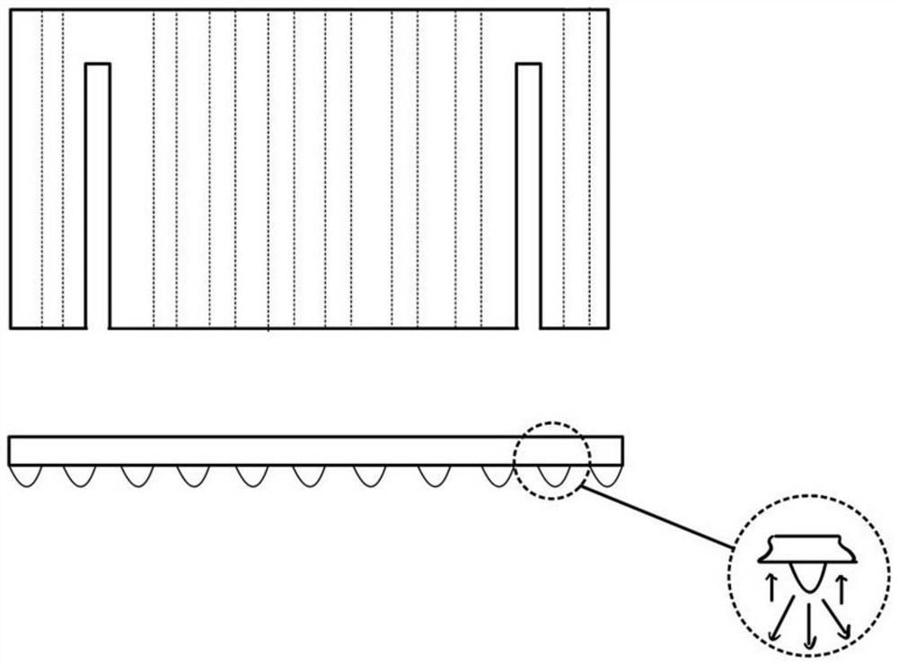
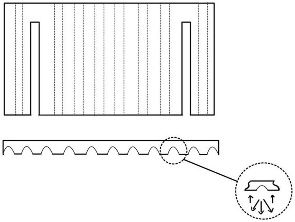
[0034] The experimental operating environment is 201°C, and the working frequency of the ultrasonic transducer is f=65.0KHz. The objects to be cleaned are metal parts with stubborn dirt such as organic oil on the surface of the parts. Choose an ultrasonic reflective cover made of metal, and choose a concave-tooth acoustic focusing structure on the lower surface of the reflective cover, and apply ultrasonic waves for ultrasonic cleaning. Compared with the control group without ultrasonic reflection cover installed at the same cleaning time and power, the cleaning efficiency increased by 37.3%.

[0035] Due to the application of the above technical solution, the present invention has the following advantages compared with the prior art: on the basis of not changing the structure of the existing ultrasonic cleaning device, by adding a top cover, the surface tension wave and the atomization effect can be effectively reduced. Acoustic energy dissipation, simple structure, easy ins...


PUM


Abstract

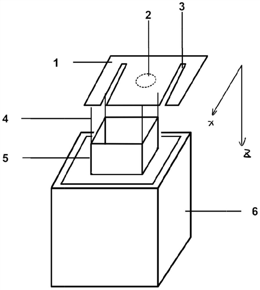
The invention discloses a sound reflection top cover structure for an ultrasonic cleaning device, and relates to the technical field of ultrasonic cleaning. On the basis that the structure of an existing ultrasonic cleaning device is not changed, the top cover is additionally arranged, so that acoustic energy dissipation caused by the tension wave of the excited gas-liquid interface and the atomization effect can be effectively reduced. Comprising a sound reflection top cover and a two-dimensional motion platform, and the bottom surface of the sound reflection top cover is a plane or is provided with a microstructure for enhancing ultrasonic diffuse reflection; and the sound reflection top cover is driven by the two-dimensional motion platform and is put into the cleaning liquid in the cleaning tank. The top cover is simple in structure and convenient to install, and the cleaning efficiency of the large ultrasonic cleaning device can be conveniently and effectively improved.

Description

technical field [0001] The invention relates to the technical field of ultrasonic cleaning, in particular to an acoustic reflection roof structure for an ultrasonic cleaning device. Background technique [0002] Ultrasonic cleaning technology first appeared in the 1930s, and its extensive research and application has never been interrupted. Ultrasonic cleaning has only a few decades of history, but its superior performance and economy have been fully demonstrated. Ultrasonic cleaning is quickly becoming an integral part of the manufacturing process for a wide variety of industries and products. [0003] At present, most of the large-scale ultrasonic cleaning devices commonly used in the industry are open without a top cover to facilitate the automatic transportation of the cleaning objects, while a small number of large-scale ultrasonic cleaning devices equipped with a protective top cover are more concerned with the airgel and dust caused by the propagation of ultrasonic w...

Claims


Application Information

Patent Timeline
IPC IPC(8): B08B3/12B08B13/00
Inventor 胡俊辉唐子豪
Owner NANJING UNIV OF AERONAUTICS & ASTRONAUTICS
Learn More