
Manufacturing method of hysteroscope head end channel

A manufacturing method and channel technology, applied in the field of hysteroscopy, can solve problems such as unreasonable use of structural space, bloated structure, and increased number of structural parts, and achieve significant promotion and application significance, better convection effect, and increased diameter upper limit.

Pending Publication Date: 2022-04-05
SHANGHAI YODO MEDICAL TECH
View PDF0 Cites 0 Cited by
  • Summary
  • Abstract
  • Description
  • Claims
  • Application Information

AI Technical Summary

Problems solved by technology

There are currently two design methods for hysteroscopes: one is with an outer sheath, and a metal sleeve is used to divide the lumen structure map. This method has unreasonable use of structural space, and the superposition of wall thickness leads to bloated structure. There are disadvantages such as increased diameter, and the disadvantages of increasing the number of structural parts, inconvenient operation, and large outer diameter; the second is the use of a one-piece mirror, but it has the disadvantage of being unable to achieve "non-planar" continuous convection
[0003] In the prior art, there is a method of adding a spacer to form an independent cavity in the middle of a round metal tube by means of internal welding, but it is found in practice that this method has defects such as difficult processing, high cost, and low yield

Method used


Image

  • Manufacturing method of hysteroscope head end channel
  • Manufacturing method of hysteroscope head end channel
  • Manufacturing method of hysteroscope head end channel

Examples


preparation example Construction

[0056] The present invention first prepares a double-channel tube, and on the basis of the formation of the double-channel tube, it also has different preparation methods for the end channels of the hysteroscopic lens, which all include the following basic steps:

[0057] S1. Prepare a hollow tube with a closed circular cross section as the base tube 1, and the inner space of the base tube 1 is used as the first channel;

[0058] In step S1, the closed ring includes but not limited to common closed shapes such as circle and square, and the base tube 1 can be prepared by one-time premolding.

[0059] S2. Prepare a segment with an arc cross section as the adapter tube 2, the segment has two opposite arc sides and two opposite straight sides;

[0060] In step S2, the segment with an arc cross section can be one of two parts cut from a complete circular tube along a certain chord line, or a rectangular or square segment can be prepared first, It is then bent into a curved tube pi...

Embodiment 1

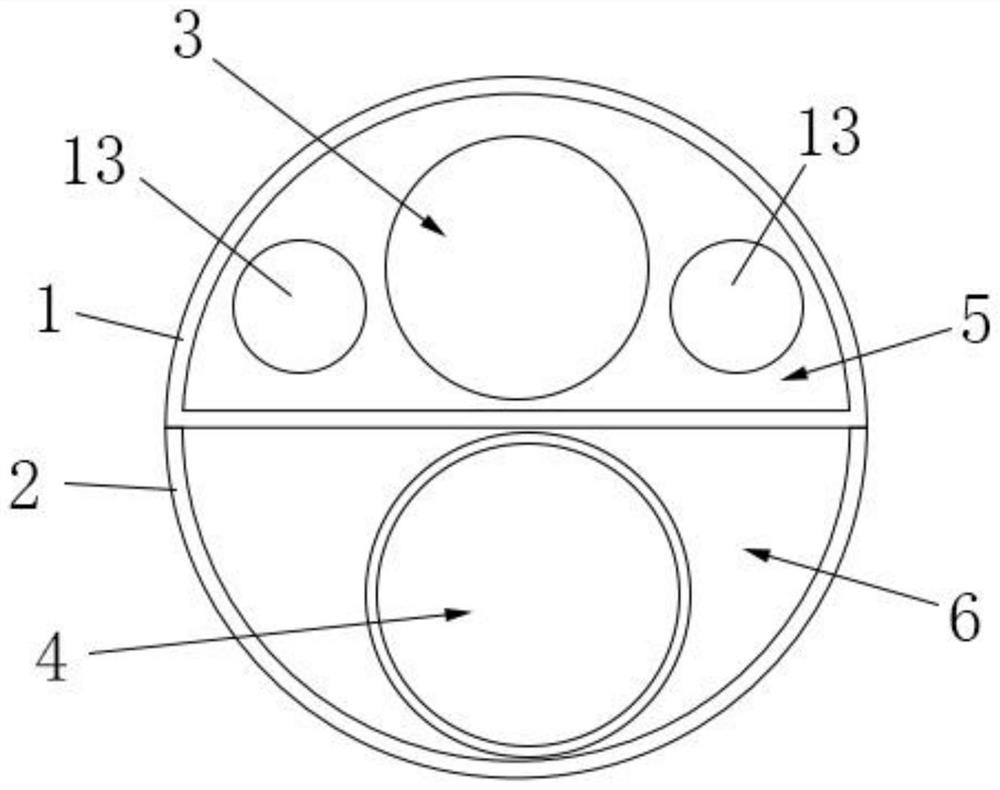
[0064] see Figure 1 to Figure 4 , in this embodiment, a method for manufacturing a hysteroscopic lens end channel with a specific structure is provided, and further improvements are made on the basic steps provided by the present invention, mainly including:

[0065] In step S1, the prepared base pipe 1 is composed of a semicircular arc surface and a plane, the cross-sectional shape of the pipe is "D", and the connection between the semicircle arc surface and the plane is two straight lines;

[0066] In step S2, the cross-sectional shape of the prepared adapter tube 2 is semicircular;

[0067] In step S3, the two straight sides of the base tube 1 and the adapter tube 2 are correspondingly fixed to form a semicircular first channel and a semicircular second channel.

[0068] As a modified embodiment of this embodiment, the manufacturing method of the hysteroscopic lens end channel provided in this embodiment is:

[0069] In step S1, the prepared base pipe 1 is composed of tw...

Embodiment

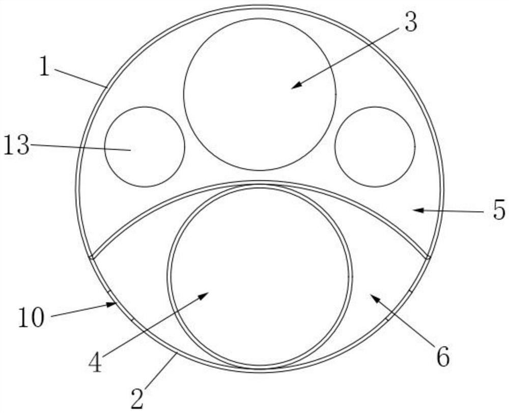
[0085] see Figure 8 to Figure 10 , in this embodiment, another method for manufacturing the end channel of the hysteroscopic lens with a specific structure is provided, which is further improved on the basic steps provided by the present invention, mainly including:

[0086] In step S1, the cross-section of the prepared base tube 1 is circular or oval;

[0087] In step S2, the prepared adapter tube 2 is sleeved on the base tube 1;

[0088] In step S3, the two straight edges of the prepared adapter tube 2 are fixed on the base tube 1 along the axis of the base tube 1, and the second channel formed is crescent-shaped.

[0089] After the above-mentioned embodiment is specifically implemented, the corresponding manufacturing method of the end channel of the hysteroscopic lens is as follows:

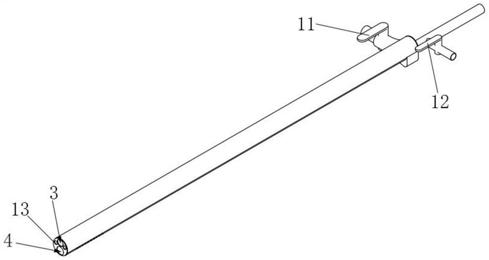
[0090] S4, using the first channel as a lens channel 3, and a lens module is arranged in the lens channel 3;

[0091] S5. Arrange an instrument channel 4 in the second channel, and arrang...


PUM


Abstract

The invention discloses a hysteroscope head end channel manufacturing method which comprises the following steps: S1, a hollow tube with a closed annular cross section is prepared as a base tube, and the internal space of the base tube is used as a first channel; s2, a segment with the arc-shaped cross section is prepared to serve as an adaptive pipe, and the segment is provided with two opposite arc-shaped edges and two opposite straight line edges; and S3, the two straight line edges of the adaptive pipe are fixed to the outer wall of the base body pipe, a hollow space with openings in the two sides is formed between the two arc-shaped edges of the adaptive pipe and the base body pipe, and the hollow space serves as a second channel. The manufacturing method of the hysteroscope head end channel is ingenious in design and reasonable in step, provides more possibilities for the layout mode of the hysteroscope front section channel, and has very remarkable popularization and application significance.

Description

technical field [0001] The invention relates to the technical field of hysteroscopes, in particular to a method for manufacturing a channel at the end of a hysteroscope. Background technique [0002] Hysteroscope is a kind of fiber light source endoscope used for inspection and treatment of uterine cavity. It uses the front part of the mirror body to enter the uterine cavity and has a magnifying effect on the observed parts. Hysteroscope needs inflow channel, outflow channel, Instrument channel and image transmission channel, etc. There are currently two design methods for hysteroscopes: one is with an outer sheath, and a metal sleeve is used to divide the lumen structure map. This method has unreasonable use of structural space, and the superposition of wall thickness leads to bloated structure. There are disadvantages such as increased diameter, and the disadvantages of increasing the number of structural parts, inconvenient operation, and large outer diameter; the second...

Claims


Application Information

Patent Timeline
Patent Type & Authority Applications(China)
IPC IPC(8): A61B1/303A61B1/015A61B1/018A61B1/00A61B1/06A61B1/04
Inventor 杨翔郝进争王臣峰
Owner SHANGHAI YODO MEDICAL TECH
Learn More