
Optical expansion waveguide

A technology of optical expansion and waveguide, applied in the field of optical expansion waveguide, can solve the problems of reducing user comfort and perception experience, increasing the volume and weight of display devices, and being unable to watch clear and good images, etc., to achieve the effect of light and thin structure

Active Publication Date: 2022-03-25
SHANGHAI RAYPAI PHOTONIC CRYSTAL LTD
View PDF7 Cites 1 Cited by
  • Summary
  • Abstract
  • Description
  • Claims
  • Application Information

AI Technical Summary

Problems solved by technology

[0004] However, due to the characteristics of this solution imaging at infinity, the display device using this solution is suitable for people with a vision of about 1.2, while the vision of the general population (including vision correction) is about 1.0, so this kind of display device is used , the wearer cannot see a clear and good image, causing great trouble to the user
In order to solve this problem, the mainstream solution is to use external devices to assist adjustment, which not only increases the size and weight of the display device, but also reduces the user's comfort and viewing experience

Method used


Image

  • Optical expansion waveguide
  • Optical expansion waveguide
  • Optical expansion waveguide

Examples


Embodiment Construction

[0039] In order to enable those skilled in the art to better understand the technical solutions in the present invention, the technical solutions in the embodiments of the present invention will be clearly and completely described below in conjunction with the drawings in the embodiments of the present invention. Obviously, the described The embodiments are only some of the embodiments of the present invention, not all of them. Based on the embodiments of the present invention, all other embodiments obtained by persons of ordinary skill in the art without making creative efforts shall fall within the protection scope of the present invention.

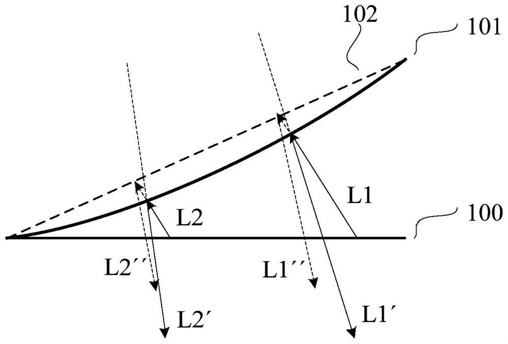
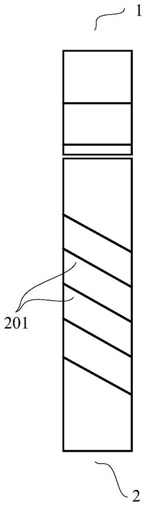
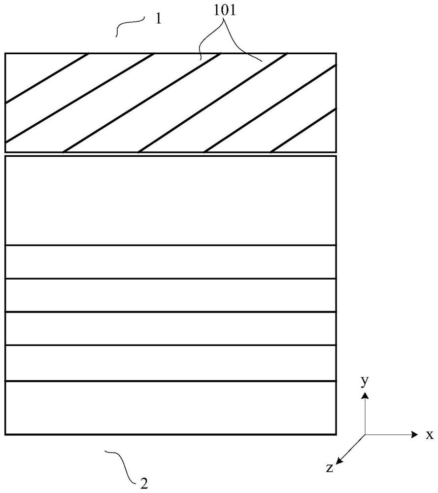
[0040] This embodiment provides an optical expansion waveguide, including a first waveguide base and a second waveguide base;

[0041] The first waveguide matrix is ​​used to expand the light beam entering the first waveguide matrix along the first dimension, and the first waveguide matrix includes a plurality of first reflective surfac...


PUM


Abstract

The invention discloses an optical expansion waveguide, which is characterized in that a first waveguide base body enables a light beam entering the first waveguide base body to be expanded along a first dimension direction, and the first waveguide base body comprises a plurality of first reflecting surfaces which are arranged in sequence, so that at least part of light is coupled into a second waveguide base body; and the second waveguide substrate enables the light beam entering the second waveguide substrate to be expanded along a second dimension direction, and the second waveguide substrate comprises a plurality of second reflecting surfaces which are arranged in sequence, so that at least part of light is emitted out of the second waveguide substrate. At least part of at least one of the first reflecting surface and the second reflecting surface is a curved surface, so that the emergent angle of the light is changed through the first reflecting surface or / and the second reflecting surface, and the image distance of an image formed by the light emitted by the second waveguide substrate meets the preset requirement. The optical expansion waveguide is applied to the optical display device, can change the image distance of an image, can be suitable for a user with abnormal vision, and is light and thin in structure.

Description

technical field [0001] The invention relates to the field of optical devices, in particular to an optical expansion waveguide. Background technique [0002] Near-eye display is an area of ​​technology that is attracting much attention today, and its optical system includes microdisplays and optical components. At present, the optical solutions for near-eye display on the market are even more controversial. [0003] Among them, the arrayed waveguide scheme uses a semi-transparent and semi-reflective optical surface to realize the expansion of the light and the exit pupil. According to the reflection law that the incident angle is equal to the reflection angle, there is no dispersion effect on the three primary colors incident light that constitutes a full-color display, so that the formed image can be guaranteed There is no obvious color deviation, which can meet the most basic requirements of the display device, and has obvious advantages in optimizing the design of the hea...

Claims


Application Information

Patent Timeline
Patent Type & Authority Applications(China)
IPC IPC(8): G02B6/10G02B27/01
CPCG02B6/10G02B27/0172
Inventor 李雨雪张文君罗豪金建虎刘瀛杨铭李伟杜俊
Owner SHANGHAI RAYPAI PHOTONIC CRYSTAL LTD
Learn More