Integrated pressure rotational flow atomizing nozzle of gas turbine and combustor with nozzle
A swirling atomizing nozzle and gas turbine technology, which is applied in the combustion chamber, combustion method, combustion equipment, etc., can solve the problems of application limitation, large overall structure and volume, and achieve compact overall size, stable combustion temperature, and reduction of nitrogen oxides. The effect of emissions
- Summary
- Abstract
- Description
- Claims
- Application Information
AI Technical Summary
Problems solved by technology
Method used
Image
Examples
Embodiment 1
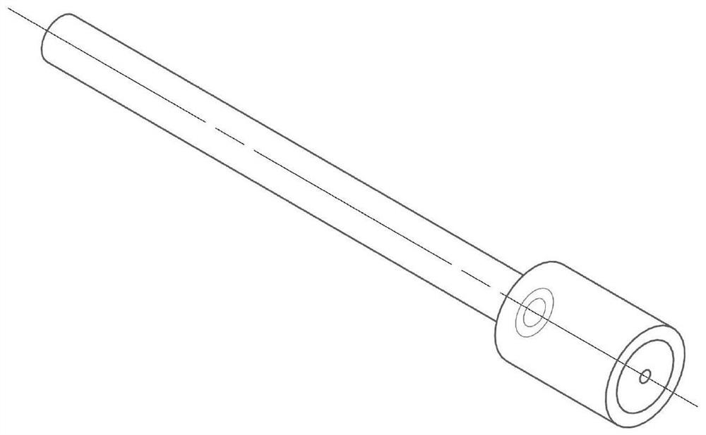
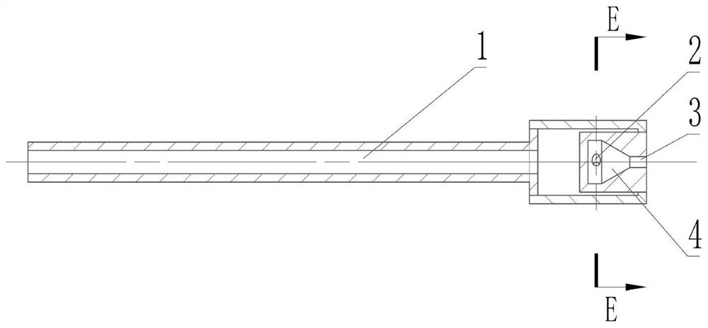
[0022] to combine Figure 1-3 , the nozzle as a whole adopts an integrated structure, including the nozzle head and the nozzle tail; the front end of the nozzle head is provided with a fuel nozzle 3, and the nozzle head is provided with a swirl chamber 4, and the fuel nozzle 3 communicates with the front end of the swirl chamber 4; There is a fuel channel 1 in the tail of the nozzle, and the fuel channel 1 communicates with the rear end of the swirl chamber 4 through the swirl hole 2; the fuel enters the cavity in the nozzle head through the fuel channel 1, and then enters through the swirl hole 2 The swirl chamber 4 is finally sprayed out in the form of oil mist through the fuel nozzle 3 .
Embodiment 2
[0024] Further, the swirl holes 2 are tangent to the inner diameter of the swirl chamber 4, and the swirl holes 2 are distributed in single or multiple rows; the number of swirl holes in each row is 2 or 3 or 4 or 6; When the flow holes 4 are distributed in multiple rows, a staggered arrangement method is adopted, and the range of the staggered angle is 0-180°.
[0025] The invention integrates the fuel channel, the swirler and the fuel nozzle, and can adjust the fuel spray pattern by changing the diameter of the swirl aperture, the number of holes, the hole position and the diameter of the fuel nozzle; due to the compact overall size, it can be conveniently used for multiple applications. in the burner. Through multi-group or multi-point arrangement, good atomization of fuel oil under different working conditions of the gas turbine can be satisfied.
Embodiment 3
[0027] Figure 4(a), Figure 4(b), Figure 5 An example of the use of the present invention is given, the example is a dual-fuel gas turbine combustor, integrated pressure swirl atomizing nozzles (invention) are installed in groups on the 2nd stage air radial swirler of the combustor (16 pieces in total, Figure 4); the fuel channel 1 is installed on the burner in the form of a plug-in connection, and communicates with the inside of the fuel main pipe; the air heat insulation tube is set on the shell at the end of the nozzle to prevent the fuel from Channel 1 carbon deposits. The fuel nozzle 3 is located at the outlet of the second-stage air radial swirler; when the dual-fuel gas turbine burner uses liquid fuel and works in a higher working condition, the high-pressure fuel from the fuel pump passes through the fuel main pipe, fuel channel 1, swirl The orifice 2 and the swirl chamber 4 are injected from the fuel nozzle 3 to the downstream of the air flow channel of the second-st...
PUM
 Abstract
Description
Claims
Application Information
 - R&D
- Intellectual Property
- Life Sciences
- Materials
- Tech Scout
- Unparalleled Data Quality
- Higher Quality Content
- 60% Fewer Hallucinations
Browse by: Latest US Patents, China's latest patents, Technical Efficacy Thesaurus, Application Domain, Technology Topic, Popular Technical Reports.
© 2025 PatSnap. All rights reserved.Legal|Privacy policy|Modern Slavery Act Transparency Statement|Sitemap|About US| Contact US: help@patsnap.com


