
Liftable wind power generation device

A technology of wind power generation device and hoisting device, which is applied in the direction of wind power generation, wind engine, wind motor combination, etc., can solve the problems of low work efficiency, loss, poor safety, etc., and achieve protection of internal equipment, reasonable structure and low failure rate low effect

Active Publication Date: 2022-03-25
江苏常友环保科技股份有限公司
View PDF6 Cites 3 Cited by
  • Summary
  • Abstract
  • Description
  • Claims
  • Application Information

AI Technical Summary

Problems solved by technology

[0004] However, in order to obtain sufficient air volume, the existing wind power generation device usually has its nacelle set at a very high place, and the equipment hoisting cost is high during installation and construction; the nacelle works at a high place, and it is difficult to observe its external conditions at close range in real time (such as surface cracks) damage, etc.); when the internal equipment needs to be repaired and maintained, the staff needs to be lifted up to the sky to carry out the work, and the replacement of spare parts also needs to be uploaded and downloaded multiple times over long distances, which has poor safety and low work efficiency; in the case of extreme weather such as strong winds However, due to its blades and huge size, the wind power generation device will bear a huge force, which is easy to be damaged and cause economic losses; more importantly, the linear velocity of the blade tip of the rotating wind power generation device is very high, Can injure birds when in the flight path of migratory flocks

Method used


Image

  • Liftable wind power generation device
  • Liftable wind power generation device
  • Liftable wind power generation device

Examples


Embodiment Construction

[0033] The following will clearly and completely describe the technical solutions in the embodiments of the present invention with reference to the drawings in the embodiments of the present invention.

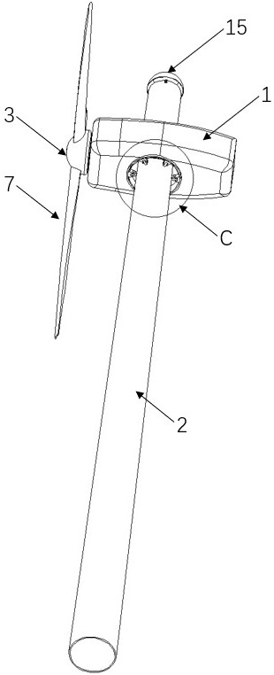
[0034] Such as Figure 1~Figure 13 As shown, a liftable wind power generation device includes a nacelle 1 and a tower 2. The tower 2 is a frame supporting the nacelle 1 of the wind power generation device. It is generally built relatively high, so as to obtain larger and more uniform wind , but also need to have sufficient strength. The central part of the nacelle 1 is vertically provided with a through hole 1a, and the tower 2 passes through the through hole 1a. The nacelle 1 and the tower 2 are slidably connected in the vertical direction, and the nacelle 1 can move up and down along the tower 2; There is a rotor hub 3 with blades 7, the rotor hub 3 rotates under the action of the wind, and converts the kinetic energy of the wind into mechanical energy; the front end of the...


PUM


Abstract

The invention relates to the technical field of wind power generation equipment, in particular to a liftable wind power generation device which comprises a cabin and a tower, a through hole is vertically formed in the middle of the cabin, the tower penetrates through the through hole, the cabin and the tower are in sliding connection in the vertical direction, a rotor hub with blades is arranged at the front end of the cabin, and the rotor hub is connected with the wind power generation device. The front end of the rotor hub is provided with a monitoring device, the rear end of the rotor hub is connected with a gearbox, the gearbox is connected with a generator, the cabin is connected with the tower through a horizontal rotating mechanism and a vertical moving mechanism, the cabin is suspended on the tower through a rope, a winding device is arranged in the tower, and the winding device is connected with the generator. The winding device drags the rope, and the monitoring device is connected into a control system of the wind power generation device. By arranging the monitoring device, the state in front of the wind power generation device is monitored in real time, and then according to different conditions, the cabin is controlled to ascend and descend along the tower through the winding device arranged in the tower and the traction rope.

Description

technical field [0001] The invention relates to the technical field of wind power generation equipment, in particular to a liftable wind power generation device. Background technique [0002] In the early 1970s, due to the "oil crisis", which caused energy shortages, human beings began to realize the instability and limitation of conventional mineral energy supply, so seeking clean and renewable energy has become an important issue in today's world. As a renewable and non-polluting energy source, wind energy has attracted more and more attention. [0003] A wind power generation device is an electrical device that converts wind energy into mechanical energy, and then converts mechanical energy into electrical energy. Broadly speaking, it is a thermal energy utilization engine that uses the sun as the heat source and the atmosphere as the working medium. Wind power utilizes natural energy and can be used for a long time. The principle of wind power generation is to use the...

Claims


Application Information

Patent Timeline
Patent Type & Authority Applications(China)
IPC IPC(8): F03D9/25F03D17/00F03D13/20F03D15/00B66D5/32
CPCF03D9/25F03D17/00F03D13/20F03D15/00B66D5/32Y02E10/72Y02E10/728
Inventor 刘文叶万慧荣岳永海
Owner 江苏常友环保科技股份有限公司
Learn More