Construction method of steel plate and concrete composite structure

A steel plate concrete and composite structure technology, applied in bridge parts, erection/assembly of bridges, bridge materials, etc., can solve the problems of prolonged construction period, inability to guarantee construction quality, low maintenance costs in the later period, etc., to improve the bearing capacity and stiffness of bridges , The overall work performance is good, the effect of shortening the construction period

Pending Publication Date: 2022-03-25
山西省交通科技研发有限公司 +1
View PDF4 Cites 1 Cited by
  • Summary
  • Abstract
  • Description
  • Claims
  • Application Information

AI Technical Summary

Problems solved by technology

[0002] Conventional small and medium-span simple-supported slab bridges are commonly used in highway bridges on common terrain, but there are the following problems. Simply-supported slab bridges can usually be divided into prefabricated and integral ones. , the horizontal connection only depends on the connection between the bridge deck system and the hinge joints, the overall horizontal connection is weak, and the construction quality cannot be guaranteed. and durability
The integral slab bridge has the advantages of good overall performance, high lateral rigidity, no need for large-scale lifting equipment and low maintenance costs in the later period, and it is easy to adapt to special terrains such as slopes, bends, and steep slopes. However, due to the need to erect supports and formwork during construction, the construction time cycle, which seriously restricts its wide application, and also brings inconvenience to later maintenance

Method used


Image

  • Construction method of steel plate and concrete composite structure
  • Construction method of steel plate and concrete composite structure
  • Construction method of steel plate and concrete composite structure

Examples


Embodiment 1

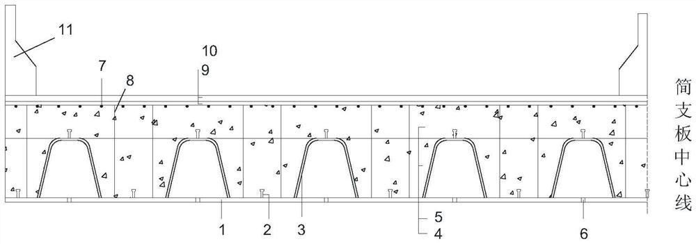
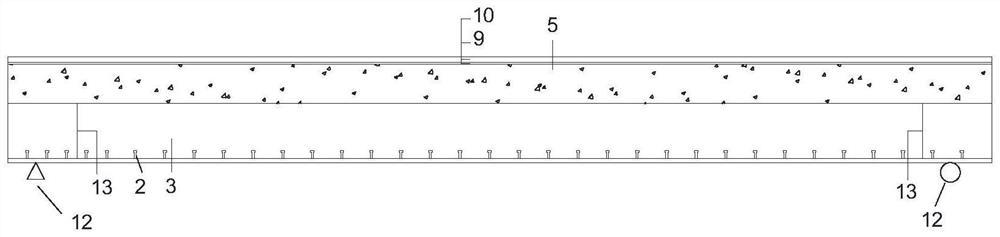
[0034] A steel plate concrete composite structure and construction method, the structure includes support, bottom steel plate, U ribs, studs, horizontal bridge end plate, longitudinal bridge end plate, stirrups, cast-in-situ main girder of the first floor from bottom to top Concrete, cast-in-place concrete for the main girder of the second floor, bridge deck pavement and guardrail, including the following steps:

[0035] (1) Through finite element calculation and analysis, the specific dimensions of each part required for the composite structure are calculated according to the specific span and width requirements of the slab bridge with the limit state method of bearing capacity, including (the size of steel plates, U ribs, and studs, pouring in stages Concrete thickness, support form, specifications, etc.).

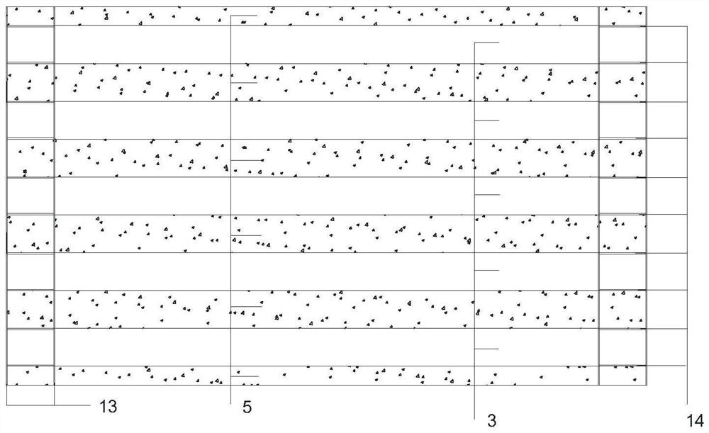
[0036] (2) Weld the bottom steel plate, U ribs, studs, and end plates on both sides in the beam field to make it a whole. For structures with large width requirements, w...


PUM


Abstract

The invention discloses a construction method of a steel plate concrete composite structure, which comprises the following steps of: combining a steel plate, a U rib and a stud to form a steel structure outer contour, pouring concrete on the steel structure outer contour part serving as a bottom template in stages to form a medium and small span steel plate concrete composite plate, and ensuring that the steel plate and the concrete do not slip through the stud. According to the technical scheme, the steel structure and the supporting structure work cooperatively, the steel structure cannot generate overlarge deflection due to the wet weight of concrete in the construction process by means of large rigidity of the steel structure and a mode of pouring concrete in batches, and therefore the purpose that a support does not need to be erected on the lower portion in the construction process is achieved. According to the structure, the defects that common small and medium span prefabricated simply-supported plates are weak in transverse connection, and cast-in-place simply-supported plate bridges are large in dead weight and inconvenient to construct are overcome, the dead weight of the structure is effectively reduced, a support does not need to be erected, construction and emergency repair of highway bridges under the condition that traffic is not affected are facilitated, the service life is longer than that of traditional simply-supported plate bridges, and the construction cost is reduced. And the later operation and maintenance cost is reduced.

Description

technical field [0001] The invention belongs to the technical field of bridge engineering, and in particular relates to a construction method of a steel plate concrete composite structure. Background technique [0002] Conventional small and medium-span simple-supported slab bridges are commonly used in highway bridges on common terrain, but there are the following problems. Simply-supported slab bridges can usually be divided into prefabricated and integral ones. , the horizontal connection only depends on the connection between the bridge deck system and the hinge joints, the overall horizontal connection is weak, and the construction quality cannot be guaranteed. and durability. The integral slab bridge has the advantages of good overall performance, high lateral rigidity, no need for large-scale lifting equipment and low maintenance costs in the later period, and it is easy to adapt to special terrains such as slopes, bends, and steep slopes. However, due to the need to...

Claims


Application Information

Patent Timeline
Patent Type & Authority Applications(China)
IPC IPC(8): E01D19/12E01D21/00E01D101/26
CPCE01D19/125E01D21/00E01D2101/268
Inventor 汪贤安李永东许军刘志华张利郭文龙赵晓晋郭学兵张川川吴焱吴佳佳毛敏李丹梅苏晓潇刘佳王星
Owner 山西省交通科技研发有限公司
Why Eureka
Try Eureka