Indoor wall surface high-position trepanning equipment
An inner wall, high-level technology, applied in stone processing equipment, stone processing tools, work accessories, etc., can solve problems such as danger, and achieve the effect of avoiding head warping
- Summary
- Abstract
- Description
- Claims
- Application Information
AI Technical Summary
Problems solved by technology
Method used
Image

Examples
Embodiment 1
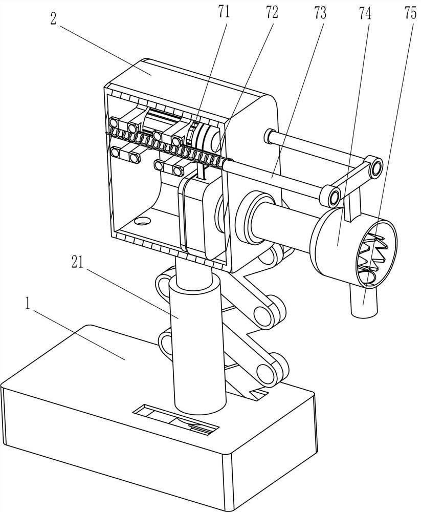
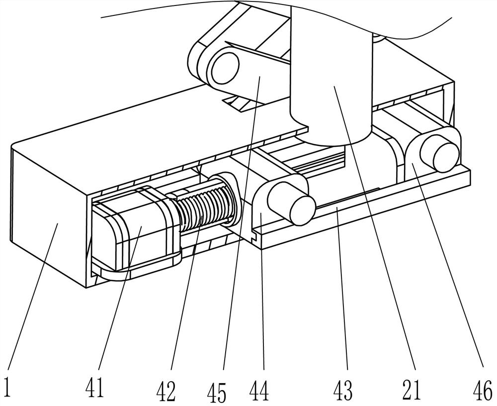
[0030] A device for opening holes at high places on indoor walls, such as Figure 1-Figure 5 As shown, it includes a first fixed frame 1, a second fixed frame 2, a telescopic rod 21, a hole-turning knife 3, a driving mechanism 4 and a hole-turning mechanism 5, and a telescopic rod is fixed on the left middle side of the outer top of the first fixed frame 1. 21. The top of the telescopic rod 21 is fixedly connected with the second fixed frame 2, and the lower side of the left part of the second fixed frame 2 is rotatably provided with a hole-turning knife 3, which can make holes on the wall surface. On the first fixed frame 1 A driving mechanism 4 is provided, and the driving mechanism 4 can realize adjusting the height position of the hole turning knife 3. The driving mechanism 4 is connected to the second fixed frame 2 in rotation, and a hole turning mechanism 5 is arranged between the second fixed frame 2 and the hole turning knife 3. The hole turning mechanism 5 can realize...
Embodiment 2
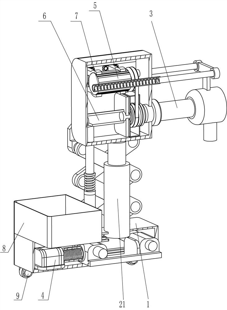
[0035] On the basis of Example 1, such as image 3 and Figure 6 As shown, it also includes an ejector mechanism 6, and the ejector mechanism 6 includes a piston rod 61, a first hollow tube 62, an ejector rod 63, a piston barrel 64 and a first spring 65, and the outer top of the first fixed frame 1 is fixed in the middle There is a piston rod 61, the second fixed frame 2 bottom is fixedly connected with the first hollow tube 62, the first hollow tube 62 corresponds to the hole cutter 3, and the first hollow tube 62 is slided and rotated to be provided with a push rod 63. The rod 63 can realize the ejection of sundries in the hole cutter 3, the ejector rod 63 will pass through the hole cutter 3, the upper part of the piston rod 61 is slidably fitted with a piston barrel 64, the piston barrel 64 communicates with the first hollow tube 62, and the piston The barrel 64 is also fixedly connected with the second fixed frame 2 , and a first spring 65 is wound between the bottom of t...
Embodiment 3
[0040] On the basis of embodiment 1 and embodiment 2, such as image 3 and Figure 8 As shown, it also includes a weight-increasing device 8, which includes a weight-increasing frame 81, a second fixed block 82 and a limit rod 83, and a weight-increasing frame 81 is placed on the right side of the outer top of the first fixed frame 1, which can Placing an appropriate amount of counterweight in the weight-increasing frame 81 can avoid head tilting. The lower part of the outer left side of the weight-increasing frame 81 is fixed with a second fixed block 82 symmetrically front and back, and the middle part of the second fixed block 82 is fixed with a limit rod 83. The limit rod 83 is connected to the first fixing frame 1 through bolts.
[0041] Such as image 3 and Figure 8 As shown, the mobile device 9 is also included. The mobile device 9 includes a third fixed block 91, a rotating rod 92 and a pulley 93. The outer bottom of the first fixed frame 1 is fixedly connected wit...
PUM
 Abstract
Description
Claims
Application Information
 - Generate Ideas
- Intellectual Property
- Life Sciences
- Materials
- Tech Scout
- Unparalleled Data Quality
- Higher Quality Content
- 60% Fewer Hallucinations
Browse by: Latest US Patents, China's latest patents, Technical Efficacy Thesaurus, Application Domain, Technology Topic, Popular Technical Reports.
© 2025 PatSnap. All rights reserved.Legal|Privacy policy|Modern Slavery Act Transparency Statement|Sitemap|About US| Contact US: help@patsnap.com