Metal processing machine tool with automatic tool changing function

A technology for metal processing and automatic tool change, which is applied in the direction of metal processing machinery parts, metal processing equipment, manufacturing tools, etc. It can solve problems such as difficult operation, time-consuming, and damage to metal processing machine tools, so as to save time, reduce costs, and realize Intelligent effect

Pending Publication Date: 2022-03-25
深圳市增创自动化机械有限公司
View PDF5 Cites 0 Cited by
  • Summary
  • Abstract
  • Description
  • Claims
  • Application Information

AI Technical Summary

Problems solved by technology

[0004] 1. In the existing metal processing machine tools, when the life of the tool ends, the tool breaks or the tool breaks due to stress, a technician or operator is required to manually change the tool, which may cause the processing machine to collide or The tool does not match, resulting in damage or shutdown of the metal processing machine tool, and the tool change process lasts too long, which consumes a lot of man-hours. After the tool change, a test tool is required. The steps are cumbersome and difficult to operate.
[0005] 2. When the existing metal processing machine tool is changed, it needs to take out the tool frequently. This process will delay time. The metal processing machine tool needs to be paused during the tool removal process, and the placement of the tool is complicated. It needs a special tool room to store and record by a special person Take care and be responsible for taking it, the tool will be damaged during the process of picking and placing the tool, and the risk factor will increase

Method used


Image

  • Metal processing machine tool with automatic tool changing function
  • Metal processing machine tool with automatic tool changing function
  • Metal processing machine tool with automatic tool changing function

Examples


Embodiment Construction

[0036] The present invention will be described in detail below, and the technical solutions in the embodiments of the present invention will be clearly and completely described. Obviously, the described embodiments are only some of the embodiments of the present invention, not all of them. Based on the embodiments of the present invention, all other embodiments obtained by persons of ordinary skill in the art without making creative efforts belong to the protection scope of the present invention.

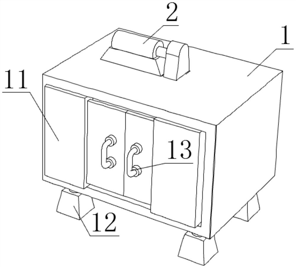
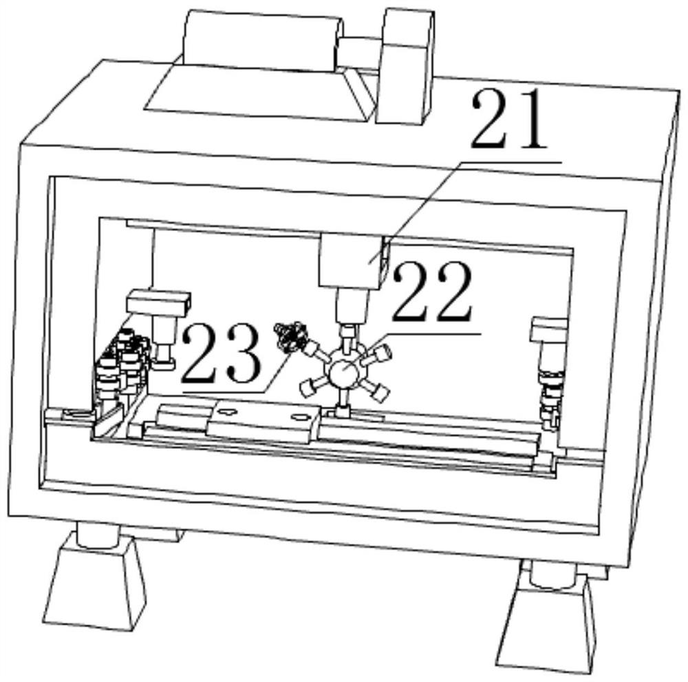
[0037] The present invention provides a kind of metal processing machine tool with automatic tool changing function through improving here, as Figure 1-Figure 11 As shown, a metal processing machine tool with an automatic tool change function includes an overall frame 1 and a power unit 2 arranged on the upper end of the overall frame 1. The power unit 2 includes a traverse lifting assembly 21, and the lower end of the traverse lifting assembly 21 is equipped with a rotating Compon...


PUM


Abstract

The invention relates to the technical field of machine tool machining, in particular to a metal machining machine tool with an automatic tool changing function, the metal machining machine tool comprises an integral frame and a power device arranged at the upper end of the integral frame, the power device comprises a transverse moving lifting assembly, and a rotating assembly is installed at the lower end of the transverse moving lifting assembly. A motor is started, the motor rotates a first belt, the first belt rotates a second wheel disc, the second wheel disc rotates a second belt, and the second belt rotates a third wheel disc, so that a rubber cutter disc rotates, a cutter body at the upper end of the rubber cutter disc rotates, and when a cutter model processor is matched with a cutter model electronic tag, the motor stops working; according to the device, the rubber cutter disc is used in cooperation with the motor, and the cutter model processor and the cutter model electronic tag are arranged, so that intelligence is achieved, and the cost is reduced.

Description

technical field [0001] The invention relates to the technical field of machine tool processing, in particular to a metal processing machine tool with an automatic tool changing function. Background technique [0002] Machine tool processing refers to the process of relying on the machine tool to ensure the relative motion relationship between the tool and the fixture, and at the same time use the tool to process the workpiece installed on the fixture, but this process is not necessarily cutting or pressure processing. In order to process the workpiece, the machine tool is on the workpiece There is a relative movement between the cutting tool and the cutting tool. This movement can be divided into main movement and feed movement. These two movements overlap together to make it possible to process raw materials. CNC machine tools automatically process according to the pre-programmed processing program. To process the parts to be processed, we write the processing route, proces...

Claims


Application Information

Patent Timeline
IPC IPC(8): B23Q3/155
CPCB23Q3/1552B23Q3/1554Y02P70/10
Inventor 贺从中李赛平黄志兵刘乐泉
Owner 深圳市增创自动化机械有限公司
Why Eureka
Try Eureka