
Non-stationary channel simulation method and system based on flight simulation platform

A flight simulation platform and channel simulation technology, applied in the field of channel simulation

Active Publication Date: 2022-03-22
CHINA ELECTRONICS TECH GRP NO 7 RES INST
View PDF8 Cites 2 Cited by
  • Summary
  • Abstract
  • Description
  • Claims
  • Application Information

AI Technical Summary

Problems solved by technology

[0009] The present invention provides a non-stationary channel simulation method based on a flight simulation platform and its system in order to solve the above-mentioned deficiencies in the prior art

Method used


Image

  • Non-stationary channel simulation method and system based on flight simulation platform
  • Non-stationary channel simulation method and system based on flight simulation platform
  • Non-stationary channel simulation method and system based on flight simulation platform

Examples


Embodiment 1

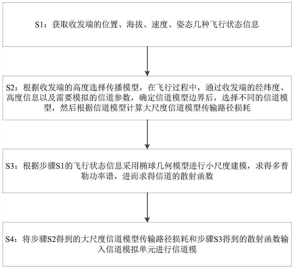
[0097] Such as figure 1 Shown, a kind of non-stationary channel simulation method based on flight simulation platform, described method comprises steps as follows:

[0098] S1: Acquiring the flight status information of the transceiver end such as position, altitude, speed and attitude through the flight simulation unit; the transceiver end described in this embodiment is two aircrafts, one is the sending end and the other is the receiving end. The line parameter generation unit is used to provide the flight status information of the transceiver, and to simulate the virtual position of the transceiver.

[0099] The row parameter generation unit described in this embodiment is based on the X-Plane flight simulation software for secondary development, and is dynamically loaded into the flight simulation software in the form of a plug-in to realize takeoff from any airport in the world, simultaneous flight of multiple aircraft, and expansion of aircraft types, etc. , and can als...

Embodiment 2

[0226] Based on the non-stationary channel simulation method based on the flight simulation platform described in embodiment 1, this embodiment also provides a non-stationary channel simulation system based on the flight simulation platform, including an integrated management unit, a flight simulation unit, a parameter calculation unit and Channel simulation units such as Figure 5 shown;

[0227] The integrated management unit is used to comprehensively control the flight simulation unit, the parameter calculation unit and the channel simulation unit, including obtaining the parameters of the flight simulation unit, calling the parameter calculation unit to calculate the parameters, and giving the calculated channel parameters to Channel simulation unit, and present the channel results;

[0228] The flight simulation unit is used to obtain several flight status information of the transceiver end, including position, altitude, speed, and attitude;

[0229] The parameter calc...


PUM


Abstract

The invention discloses a non-stationary channel simulation method and a non-stationary channel simulation system based on a flight simulation platform. The method comprises the following steps: S1, acquiring flight state information of the position, the altitude, the speed and the attitude of a receiving and transmitting end; s2, selecting a propagation model according to the height of the transmitting and receiving end, determining the boundary of a channel model through the latitude and longitude of the transmitting and receiving end, the height information and channel parameters needing to be simulated in the flight process, selecting different channel models, and then calculating the transmission path loss of a large-scale channel model according to the channel models; s3, performing small-scale modeling by adopting an ellipsoid geometric model according to the flight state information in the step S1, obtaining a Doppler power spectrum, and further obtaining a scattering function of a channel; and S4, inputting the transmission path loss of the large-scale channel model obtained in the step S2 and the scattering function obtained in the step S3 into a channel simulation unit for channel mode. The method overcomes the defects of few actual measurement test opportunities, high cost and the like of the aeronautical communication equipment.

Description

technical field [0001] The present invention relates to the technical field of channel simulation, and more specifically, to a non-stationary channel simulation method and system based on a flight simulation platform. Background technique [0002] The traditional aeronautical telecommunication network (Aeronautical Telecommunication Network, ATN) is a ground-centered communication method, which does not allow direct communication between aircraft. In areas without base station coverage, aircraft communication can only rely on satellites. The high cost of communication makes it difficult for many network applications (such as Internet access, black box data transmission, etc.) to be used on a large scale in the civil aviation field. In addition, in the next two decades, the low-altitude open policy will be gradually implemented in countries around the world, and the flying activities of small and medium-sized general-purpose aircraft in low-altitude airspace will surge. Howe...

Claims


Application Information

Patent Timeline
IPC IPC(8): H04B17/309H04B17/391
CPCH04B17/309H04B17/3912Y02D30/70
Inventor 水宜水卢毅张欣徐林程晓洁
Owner CHINA ELECTRONICS TECH GRP NO 7 RES INST
Learn More