
Resonator used as radio frequency front-end surface acoustic wave filter

A surface acoustic wave and radio frequency front-end technology, applied in the field of resonators, can solve the problems of composite substrate resonator and filter performance impact, and achieve the effect of suppressing lateral parasitic mode, small ripple, and eliminating parasitic lateral mode

Inactive Publication Date: 2022-03-22
CHENGDU PINNACLE MICROWAVE CO LTD
View PDF9 Cites 2 Cited by
  • Summary
  • Abstract
  • Description
  • Claims
  • Application Information

AI Technical Summary

Problems solved by technology

[0004] In view of the above-mentioned deficiencies in the prior art, a resonator used as a radio frequency front-end surface acoustic wave filter provided by the present invention can effectively suppress the lateral spurious mode, and solve the problem that the performance of the composite substrate resonator and filter is affected by the lateral spurious mode The problem

Method used


Image

  • Resonator used as radio frequency front-end surface acoustic wave filter
  • Resonator used as radio frequency front-end surface acoustic wave filter
  • Resonator used as radio frequency front-end surface acoustic wave filter

Examples


Embodiment 1

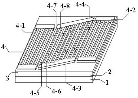
[0035] A resonator used as a surface acoustic wave filter in an RF front-end, such as figure 1 As shown, it includes: a composite substrate, a piezoelectric layer 3 located on the upper surface of the composite substrate, and an interdigital transducer layer 4 disposed on the piezoelectric layer 3 .

[0036] The interdigital transducer layer 4 is provided with a main body of the interdigital transducer.

[0037] The main body of the finger transducer includes: a first bus bar 4-3, a second bus bar 4-4, at least one first electrode long finger 4-5 connected to the first bus bar 4-3, and a first electrode long finger 4-5 connected to the first bus bar At least one first electrode short finger 4-6 connected to 4-3, at least one second electrode short finger 4-7 connected to the second bus bar 4-4 and at least one first electrode short finger connected to the second bus bar 4-4 Two electrode long fingers 4-8;

[0038] All the long fingers 4-5 of the first electrodes are adjacent...

Embodiment 2

[0042] On the basis of the above-mentioned embodiment 1, there is a longitudinal displacement between the ends of all the nearest two first electrode long fingers 4-5, and there is a longitudinal displacement between the ends of all the nearest two second electrode long fingers 4-8. There is also a longitudinal displacement between them; the range of all longitudinal displacements is from 0.05 times the wavelength to 0.2 times the wavelength.

Embodiment 3

[0044] On the basis of the above-mentioned embodiment 2, all the first electrode long fingers 4-5 and the first electrode short fingers 4-6 are connected to the first bus bar 4-3 with connection angles, and all the second electrodes The connection angle between the short finger 4-7 and the second electrode long finger 4-8 and the second bus bar 4-4 is also set, and all the connection angles are the same, and the value ranges from 80° to 100°.


PUM


Abstract

The invention discloses a resonator used as a radio frequency front-end surface acoustic wave filter, which relates to the field of resonators and comprises a composite substrate, a piezoelectric layer located on the upper surface of the composite substrate and an interdigital transducer layer arranged on the piezoelectric layer, and an interdigital transducer main body is arranged in the interdigital transducer layer. According to the invention, through the longitudinal displacement between the ends of the interdigitated fingers in the interdigitated transducer main body and the angle design between the interdigitated fingers and the bus bar, the acoustic characteristics of the surface acoustic resonator are improved, and the transverse parasitic mode is suppressed, so that the radio frequency front-end filter adopting the interdigitated transducer is flat in transmission band and small in ripple.

Description

technical field [0001] The invention relates to the field of resonators, in particular to a resonator used as a radio frequency front-end surface acoustic wave filter. Background technique [0002] The rapid development of mobile communication technology, especially the comprehensive advancement of 4G communication represented by high data traffic transmission in the past few years, has driven the vigorous development of the smart phone terminal market. As far as wireless communication is concerned, the RF front-end is the core of wireless communication, in which filters play a vital role. With the development of communication technology from 2G to 5G, the number of communication frequency bands has gradually increased (from 4 frequency bands in 2G to more than 50 frequency bands in 5G). Each frequency band requires at least one filter, and the amount of filters will increase explosively in the future. [0003] The current filter usually grows electrodes on the piezoelectr...

Claims


Application Information

Patent Timeline
Patent Type & Authority Applications(China)
IPC IPC(8): H03H9/25H03H9/02H03H9/145
CPCH03H9/6489H03H9/6496H03H9/25H03H9/02574H03H9/02834H03H9/14547
Inventor 莫兴泽柳嵩董元旦杨涛马增红
Owner CHENGDU PINNACLE MICROWAVE CO LTD
Learn More