Dry-type fluorescence immunoassay analyzer based on multi-channel and automatic detection
A fluorescent immunoassay and automatic detection technology, applied in the field of immune analyzers, can solve the problems of inability to realize automation, cumbersome operation, cumbersome manual steps, etc., and achieve the effect of fast and flexible integration of the whole machine
- Summary
- Abstract
- Description
- Claims
- Application Information
AI Technical Summary
Problems solved by technology
Method used
Image
Examples
Embodiment 1
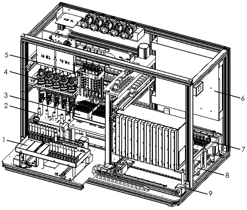
[0047] Such as figure 1 As shown, the present embodiment includes a rack, and the rack is provided with a sample module 1, a shaking module 2, a tip module 3, a cap pulling module 4, a sample adding module 5, a control module 6, an incubation module 7, a transport module 8 and reagent cartridge module 9, and the transportation module 8 is connected with the reagent cartridge module 9 and the incubation module 7 at the same time; The cap module 4 is connected to the shaking module 2, the sample module 1 is connected to the cap pulling module 4 and the shaking module 2, the sample module 1, the shaking module 2, the tip module 3, the cap pulling module 4, the sample adding module 5, the incubation The module 7, the transportation module 8 and the reagent cartridge module 9 are all connected to the control module 6. After they are arranged and connected according to the needs, they can meet the needs of use. Biomedical technology and chromatography technology are used to analyze ...
Embodiment 2
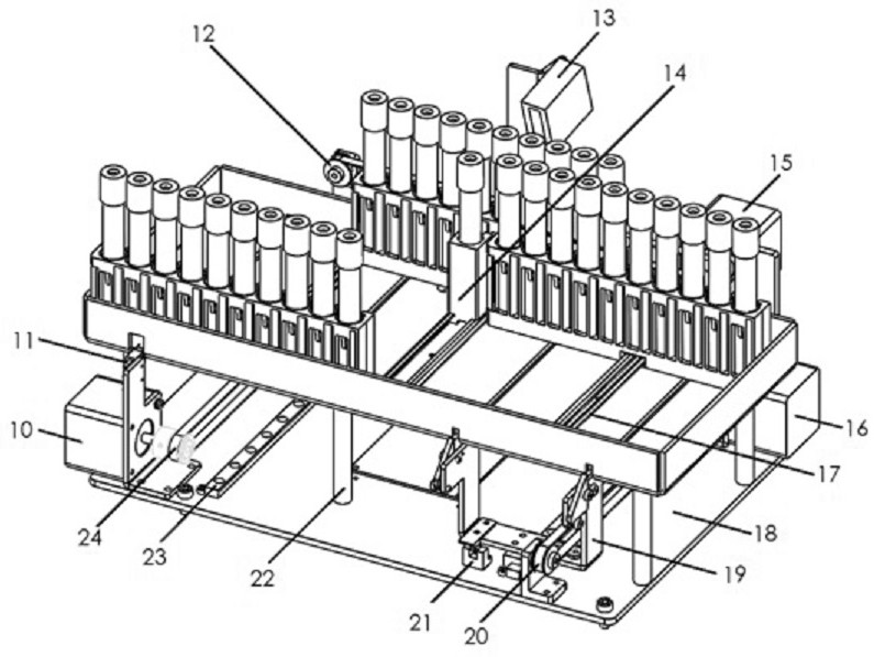
[0049] Such as figure 2 As shown, the sample module 1 of the present embodiment includes a sample rack bottom plate, and a mounting plate 18 is arranged below the sample rack bottom plate, and the mounting plate 18 and the sample rack bottom plate are supported by a column 122 to form a sufficient installation space at the bottom. The bottom plate of the rack and the frame are fixed, and a sample rack is arranged on the bottom plate of the sample rack. The sample rack has been tested, the driving mechanism 16, the timing belt pulley and the timing belt 2 20 are arranged under the bottom plate of the sample rack, the timing belt is connected with the sampling fork 19, and the sampling fork 19 is located in the corresponding slideway opened on the bottom plate of the sample rack , the sampling fork 19 can move along the slideway. The sample injection fork 19 is connected with the first guide rail, and the sample injection fork 19 can move along the first guide rail. An optoco...
Embodiment 3
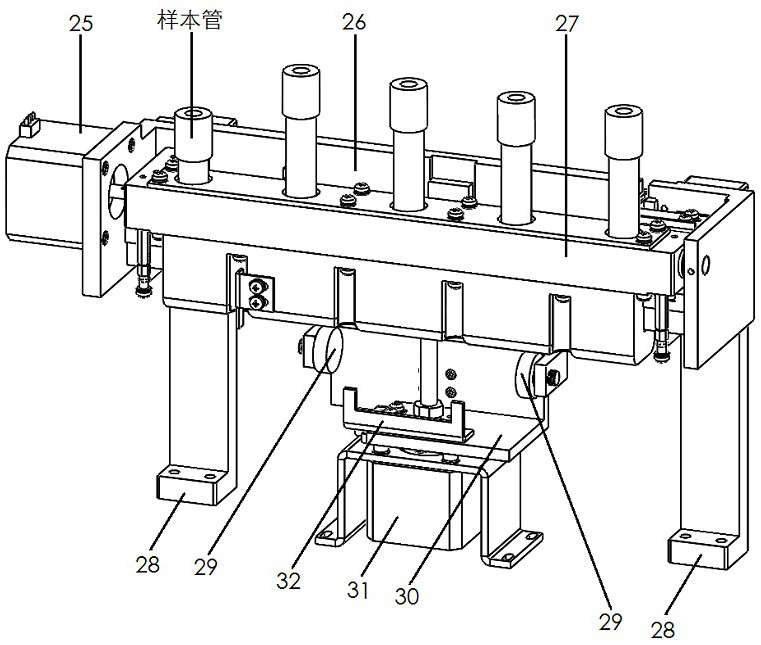
[0056] Such as image 3 As shown, the shaking module 2 includes a supporting mechanism, and the supporting mechanism is mainly composed of a shaking installation plate 26 and a shaking column 28, wherein the shaking column 28 is two pieces and is vertically arranged, and the shaking installation plate 26 is combined with the two pieces at the same time. Shake well and the column 28 is fixed. The support mechanism is provided with a shaker main body 27 and a driving mechanism 25, and the driving mechanism 25 adopts a stepping motor as a shaking drive mechanism. A through hole for installing sample test tubes is provided on the shaker main body 27, and a shaker cover plate is installed on the top surface of the shaker body 25. The shaker cover plate exposes the through hole, and a sample rack adapter is arranged on the shaker cover plate. A sample rack adapter is set at the outlet of the through hole, and the sample test tube in the through hole is fixed by the shaking cover pl...
PUM
 Abstract
Description
Claims
Application Information
 - R&D
- Intellectual Property
- Life Sciences
- Materials
- Tech Scout
- Unparalleled Data Quality
- Higher Quality Content
- 60% Fewer Hallucinations
Browse by: Latest US Patents, China's latest patents, Technical Efficacy Thesaurus, Application Domain, Technology Topic, Popular Technical Reports.
© 2025 PatSnap. All rights reserved.Legal|Privacy policy|Modern Slavery Act Transparency Statement|Sitemap|About US| Contact US: help@patsnap.com


