
Concrete formwork connecting mechanism capable of achieving rapid butt joint and locking

A technology of concrete formwork and connection mechanism, which is applied to the joints of formwork/formwork/work frame, building structure, and on-site preparation of building components. problems, to achieve the effect of convenient combination and docking, increased stability, and easy construction

Pending Publication Date: 2022-03-22
周华巍
View PDF8 Cites 1 Cited by
  • Summary
  • Abstract
  • Description
  • Claims
  • Application Information

AI Technical Summary

Problems solved by technology

[0008] The purpose of the present invention is to provide a concrete formwork connection mechanism capable of fast docking and locking, to solve the problem of inconvenient adjustment of the distance between formworks and formworks according to the actual situation during the actual construction of concrete formworks proposed by the above-mentioned background technology. The size is adjusted, and the limit effect between the formwork and the formwork is not good, and it is easy to loosen and affect the pouring of concrete. The height of the formwork is fixed, and it is inconvenient to adjust the height of the formwork according to the actual pouring situation, and the support The stability is not good, it is easy to fall, the connection and installation between the parts are not convenient, the volume is large, it is inconvenient to disassemble and carry, and it is not convenient to quickly connect the formwork with the formwork, according to the actual requirements. Combined installation, the bearing effect of the connection between the formwork and the formwork is not good, which affects the stability of the entire formwork during the pouring process

Method used


Image

  • Concrete formwork connecting mechanism capable of achieving rapid butt joint and locking
  • Concrete formwork connecting mechanism capable of achieving rapid butt joint and locking
  • Concrete formwork connecting mechanism capable of achieving rapid butt joint and locking

Examples


Embodiment Construction

[0048] The following will clearly and completely describe the technical solutions in the embodiments of the present invention with reference to the accompanying drawings in the embodiments of the present invention. Obviously, the described embodiments are only some, not all, embodiments of the present invention. Based on the embodiments of the present invention, all other embodiments obtained by persons of ordinary skill in the art without making creative efforts belong to the protection scope of the present invention.

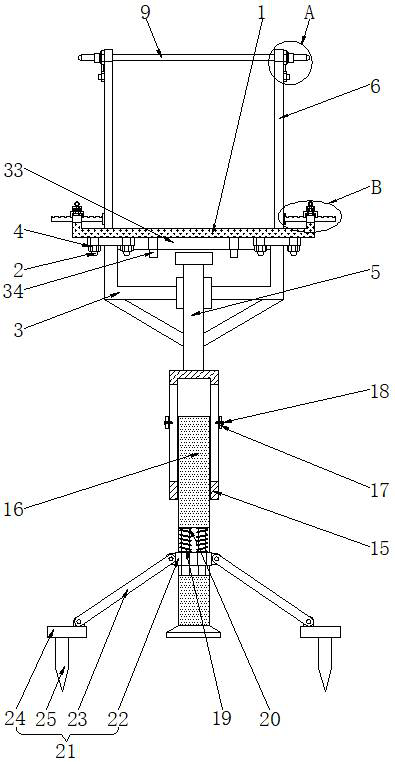
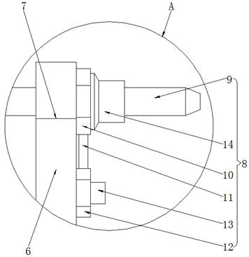
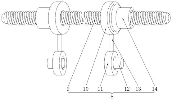
[0049] see Figure 1-11 , the present invention provides a technical solution: a concrete formwork connection mechanism capable of fast docking and locking, including a lower formwork 1, studs 2, support frames 3, fastening nuts 4, support columns 5, side formworks 6, connection grooves 7. Fixing mechanism 8, connecting rod 9, upper connecting plate 10, vertical rod 11, lower connecting plate 12, fixed plug 13, connecting sleeve 14, fixed plate 15, mounting co...


PUM


Abstract

The invention discloses a concrete formwork connecting mechanism capable of being quickly butted and locked, which comprises a lower formwork in a horizontal state, side formworks symmetrically arranged on the left side and the right side of the upper end of the lower formwork, a fixing mechanism arranged at the upper ends of the side formworks, and a fixing plate arranged at the upper ends of the side formworks. A sliding structure is formed between the fixing plate and a mounting column which is in a vertical state and has a bearing function, the limiting mechanisms are symmetrically arranged at the left end and the right end of the lower die plate, and the bearing mechanism is arranged at the lower end of the joint of the lower die plates. According to the concrete formwork connecting mechanism capable of achieving rapid butt joint and locking, the whole mechanism is good in stability and not prone to toppling over, formworks can be conveniently and rapidly combined and in butt joint, the height of the formworks can be conveniently adjusted, the fastening performance of the connecting positions of the formworks is good, and therefore the better bearing effect is achieved, and loosening is not prone to occurring.

Description

technical field [0001] The invention relates to the related technical field of concrete formwork, in particular to a concrete formwork connection mechanism capable of fast docking and locking. Background technique [0002] Concrete formwork refers to the shaping equipment built in advance through certain parts during the construction process of concrete pouring and forming. After the concrete is formed and solidified, the concrete formwork is removed from the outside of the concrete. The concrete formwork is placed in the concrete. It plays an important role in the construction process, and the concrete formwork needs to pass a certain connection mechanism to limit and support the connection between the formwork during the construction process; [0003] However, the commonly used concrete formwork connection mechanism still has the following deficiencies: [0004] 1. The existing concrete formwork connection mechanism is inconvenient to adjust the distance between the formw...

Claims


Application Information

Patent Timeline
IPC IPC(8): E04G17/00
CPCE04G17/00
Inventor 周华巍
Owner 周华巍
Learn More