
Variable-frequency resonant three-phase power factor correction converter

A three-phase power and converter technology, applied in the direction of converting AC power input to DC power output, output power conversion device, high-efficiency power electronic conversion, etc. Obstructing the increase of the switching frequency of the converter, etc., to achieve the effect of reducing pressure, high power density, and eliminating the third harmonic current

Pending Publication Date: 2022-03-18
上海钧功电子科技有限公司
View PDF0 Cites 0 Cited by
  • Summary
  • Abstract
  • Description
  • Claims
  • Application Information

AI Technical Summary

Problems solved by technology

[0004] Another problem of the three-phase power factor correction converter is the problem of efficiency and power density. The continuous current three-phase power factor correction circuit is a hard switching mode, and the existence of switching losses hinders the increase of the switching frequency of the converter.
Generally, it can only work in the frequency range of <100KHz, and the size of the magnetic components is large, which hinders the improvement of the power density of the power system

Method used


Image

  • Variable-frequency resonant three-phase power factor correction converter
  • Variable-frequency resonant three-phase power factor correction converter
  • Variable-frequency resonant three-phase power factor correction converter

Examples


Embodiment Construction

[0047] In order to deepen the understanding of the present invention, the present invention will be further described below in conjunction with the examples, which are only used to explain the present invention, and do not constitute a limitation to the protection scope of the present invention.

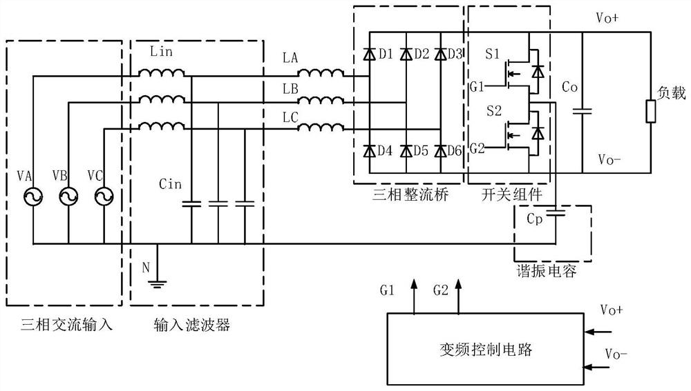
[0048] Please refer to figure 1 , The variable frequency resonant three-phase power factor correction converter of the first embodiment of the present invention includes: an input filter, a set of input inductors, a three-phase rectifier bridge, a switch assembly, an output capacitor, a resonant capacitor and a variable frequency control circuit.

[0049] The input filter is composed of three inductors Lin and three capacitors Cin, which respectively filter the three-phase input voltages VA, VB, and VC. The three-phase AC input voltage VA, VB, VC adopts a three-phase four-wire system. The three-phase input voltage VA, VB, and VC lines are respectively connected to three inductors Lin...


PUM


Abstract

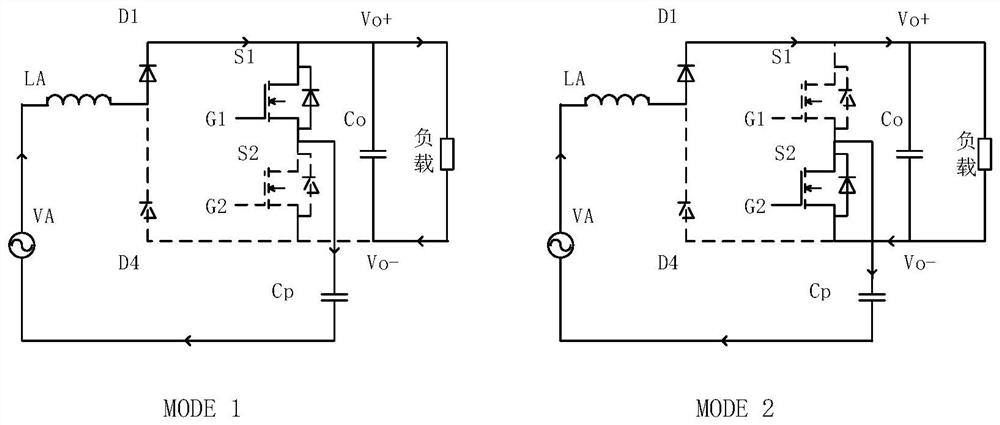
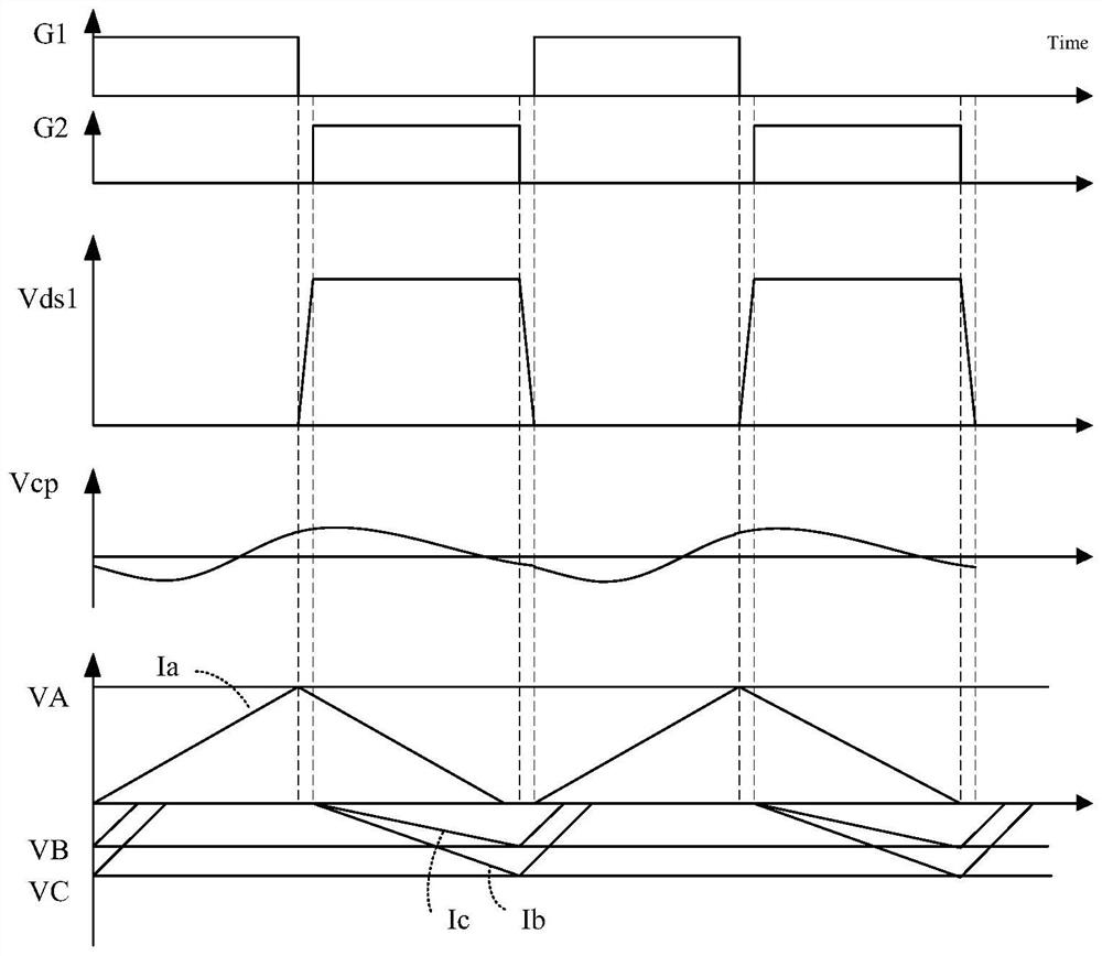
The invention provides a variable-frequency resonant three-phase power factor correction converter, and the converter comprises an input filter which comprises three inductors and three capacitors, and carries out the filtering of a three-phase input voltage; the three input inductors respectively receive the filtered three-phase input voltage; the three-phase rectifier bridge is used for receiving the outputs of the three input inductors respectively; the switch assembly comprises a first switch and a second switch which are coupled to the two ends of the three-phase rectifier bridge and are connected in series; the output capacitor is connected to the two ends of the three-phase rectifier bridge in parallel; one end of the resonant capacitor is connected to a node between the first switch and the second switch, and the other end is connected to a zero line; and the frequency conversion control circuit is connected to the two ends of the output capacitor, detects the differential voltage at the two ends of the output capacitor and controls the on and off of the first switch and the second switch according to the differential voltage. According to the invention, the third harmonic current can be eliminated, and the THD is reduced to below 3%.

Description

technical field [0001] The invention belongs to the technical field of three-phase power factor correction converters, and more specifically relates to a frequency conversion resonant three-phase power factor correction converter. Background technique [0002] The power factor correction converter (PFC) is a power conversion device that converts single-phase or three-phase AC voltage into DC voltage, and at the same time realizes an ideal power factor (PF=1) close to 1 to reduce the reactive current of the grid And the total harmonic current (THD), to realize the friendly intervention of electrical equipment to the grid. [0003] For three-phase power factor correction converters, there are many kinds of circuit topologies for active power factor converters characterized by high-frequency switching. Through precise regulation of the three-phase input current, the three-phase current and its corresponding three-phase voltage can be strictly aligned. Proportional relationship...

Claims


Application Information

Patent Timeline
Patent Type & Authority Applications(China)
IPC IPC(8): H02M7/217H02M1/088H02M1/42H02M1/12H02M1/14
CPCH02M7/217H02M1/088H02M1/4241H02M1/12H02M1/14Y02B70/10
Inventor 黄贵松胡建林刘历川
Owner 上海钧功电子科技有限公司
Learn More