
Low-energy-consumption ammonia-carbon separation method

A technology of ammonia-carbon separation and low energy consumption, which is applied in the preparation/separation of ammonia, chemical instruments and methods, carbon compounds, etc. It can solve the problems of difficult operation and high energy consumption, and achieve energy consumption reduction, steam consumption reduction, and liquid reduction The effect of circulation volume

Pending Publication Date: 2022-03-18
ANHUI JINGHE IND
View PDF7 Cites 0 Cited by
  • Summary
  • Abstract
  • Description
  • Claims
  • Application Information

AI Technical Summary

Problems solved by technology

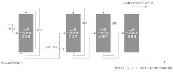
[0007] The purpose of the present invention is to provide a low-energy ammonia-carbon separation method in order to solve the problems of high energy consumption and difficult operation in the existing ammonia-carbon tail gas separation technology; the method sends the mixed gas containing ammonia and carbon dioxide into multiple Level carbon dioxide absorption tower, the absorption tower uses dilute ammonia water as the absorption liquid, and absorbs it countercurrently from low concentration to high concentration, so that the absorption can obtain methylammonium liquid, and the methylammonium liquid is separated through the multi-stage carbon dioxide separation tower, so as to realize the separation of ammonia and carbon dioxide the goal of

Method used


Image

  • Low-energy-consumption ammonia-carbon separation method

Examples


Embodiment 1

[0024] (1) The mixed gas containing ammonia and carbon dioxide (including NH 3 63%, CO 2 37%) into the bottom of the primary carbon dioxide absorption tower at 74000 L / min, and add dilute ammonia water with a concentration of 4wt% at 80L / min from the middle of the primary carbon dioxide absorption tower as the absorption liquid, and the mixed gas and dilute ammonia water are in the absorption tower Circulate and absorb in a countercurrent manner for 20 minutes;

[0025] (2) After the cycle is over, the absorption liquid in the primary carbon dioxide absorption tower (ammonia / carbon mass ratio is 3:1 carbonized ammonia water) is sent to the middle of the secondary carbon dioxide absorption tower at 80 L / min, and the top of the primary carbon dioxide absorption tower The unabsorbed gas (including NH 3 45%, CO 2 54%) into the bottom of the secondary carbon dioxide absorption tower at 50,000 L / min, and circulate and absorb in the absorption tower for 20 minutes in a counter...

Embodiment 2

[0028] ( ) Mixed gas containing ammonia and carbon dioxide (containing NH 3 60%, CO 2 39%) into the bottom of the primary carbon dioxide absorption tower at 75000 L / min, and add dilute ammonia water with a concentration of 3.5wt% from the middle of the primary carbon dioxide absorption tower at 60 L / min as the absorption liquid, and the mixed gas and dilute ammonia water are absorbed Circulate and absorb in the tower in a countercurrent manner for 40 min;

[0029] (2) After the cycle is over, the absorption liquid in the primary carbon dioxide absorption tower (the ammonia / carbon mass ratio is 4:1 carbonized ammonia water) is sent to the middle of the secondary carbon dioxide absorption tower at 60 L / min, and the top of the primary carbon dioxide absorption tower The unabsorbed gas (including NH 3 40%, CO 2 59%) into the bottom of the secondary carbon dioxide absorption tower at 50,000 L / min, and circulate and absorb in the absorption tower for 40 minutes in a countercu...

Embodiment 3

[0032](1) The mixed gas containing ammonia and carbon dioxide (including NH 3 63%, CO 2 38%) into the bottom of the primary carbon dioxide absorption tower at 77000 L / min, and add dilute ammonia water with a concentration of 5wt% from the middle of the primary carbon dioxide absorption tower at 50-100L / min as the absorption liquid, and the mixed gas and dilute ammonia water are Circulate absorption in the absorption tower for 60 minutes in a countercurrent manner;

[0033] (2) After the cycle is over, the absorption liquid in the primary carbon dioxide absorption tower (ammonia / carbon mass ratio is 3:1 carbonized ammonia water) is sent to the middle of the secondary carbon dioxide absorption tower at 100 L / min, and the top of the primary carbon dioxide absorption tower The unabsorbed gas (including NH 3 35%, CO 2 63%) into the bottom of the secondary carbon dioxide absorption tower at 50,000 L / min, and circulate and absorb in the absorption tower for 60 minutes in a cou...


PUM


Abstract

The invention relates to a low-energy-consumption ammonia-carbon separation method which is characterized in that mixed gas of ammonia and carbon dioxide and dilute ammonia water are sequentially fed into a first-stage carbon dioxide absorption tower and a second-stage carbon dioxide absorption tower, and the mixed gas and the dilute ammonia water are circularly absorbed in the absorption towers in a countercurrent manner; the absorbed gas-liquid mixture is sequentially fed into a first-stage carbon dioxide separation tower and a second-stage carbon dioxide separation tower to be separated, the pressure of the first-stage carbon dioxide separation tower is controlled to be 0.2-0.5 Mpa, the pressure of the second-stage carbon dioxide separation tower is controlled to be 0.6-1.2 Mpa, the temperature of the first-stage carbon dioxide separation tower is controlled to be 80-100 DEG C, the temperature of the second-stage carbon dioxide separation tower is controlled to be 115-135 DEG C, carbon dioxide with the ammonia content smaller than 50 ppm and carbonized ammonia water with the ammonia / carbon mass ratio being (8-12): 1 are obtained, and the carbonized ammonia water is fed to be subjected to The method has the advantages that the steam generated by the urea washing tower of the melamine device is used for heating the separating tower, so that the energy consumption is reduced by about 15%; and the crude ammonia gas is recycled in a steam and / or electricity consumption mode, flexible selection can be achieved in practical application, and the device is high in operability.

Description

technical field [0001] The invention belongs to the field of melamine production and relates to a method for separating ammonia and carbon with low energy consumption. Background technique [0002] Melamine (chemical formula: C 3 N 3 (NH 2 ) 3 ), commonly known as melamine, protein essence, IUPAC named "1,3,5-triazine-2,4,6-triamine", is a triazine nitrogen-containing heterocyclic organic compound, used as a chemical raw material . It is white monoclinic crystal, almost odorless, slightly soluble in water (3.1g / L at room temperature), soluble in methanol, formaldehyde, acetic acid, hot glycol, glycerin, pyridine, etc., insoluble in acetone, ethers, harmful to the body Harmful, not used in food processing or food additives. [0003] In the production process of synthetic ammonia, urea, melamine, etc., a large amount of mixed gas containing ammonia and carbon dioxide will be produced. Based on economic and environmental considerations, it is usually necessary to separate...

Claims


Application Information

Patent Timeline
Patent Type & Authority Applications(China)
IPC IPC(8): C01B32/50C01C1/12
CPCC01B32/50C01C1/12
Inventor 李恩平施以军储晓晖李厚才张殿双
Owner ANHUI JINGHE IND
Learn More