Pneumatic numerical control shot blasting machine

A kind of shot blasting machine, pneumatic technology, applied in the direction of used abrasive processing device, solid separation, magnetic separation, etc., can solve the impact of steel shot on the effect of shot blasting, steel shot stuck, decrease of mesh filter effect, etc. problem, achieve the effect of reducing maintenance cost and improving service life

Pending Publication Date: 2022-03-18
刘会恺
View PDF17 Cites 0 Cited by
  • Summary
  • Abstract
  • Description
  • Claims
  • Application Information

AI Technical Summary

Problems solved by technology

[0005] Nowadays, most of the common steel shot recovery and screening devices adopt the principle of mesh screen to filter out the mixed impurities through a certain number of vibrating mesh screens to filter out the steel shots that have become smaller and fragmented, as well as metal debris, rust residue, and dust. , to obtain steel shots that can continue to be recycled, but in this way, due to the different sizes of the steel shots, some steel shots will be stuck on the mesh of the vibrating screen, and the filtering effect of the screen will decrease significantly over time, which is unqualified The steel shot will seriously affect the effect of shot blasting

Method used


Image

  • Pneumatic numerical control shot blasting machine
  • Pneumatic numerical control shot blasting machine
  • Pneumatic numerical control shot blasting machine

Examples


Embodiment approach

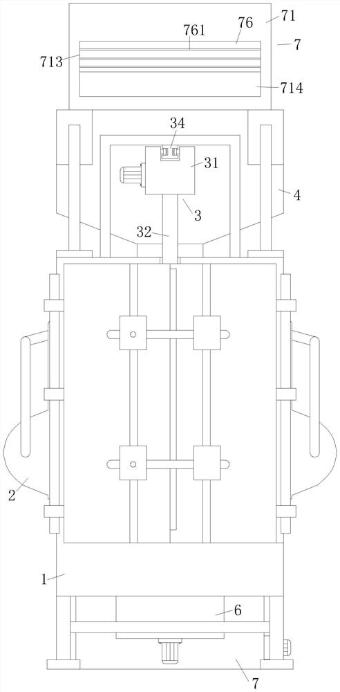
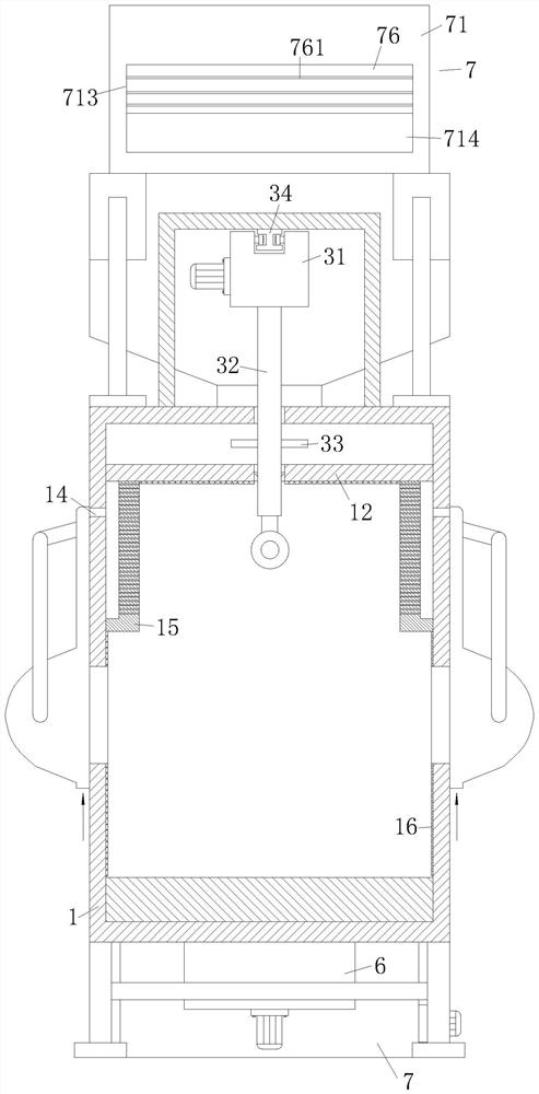
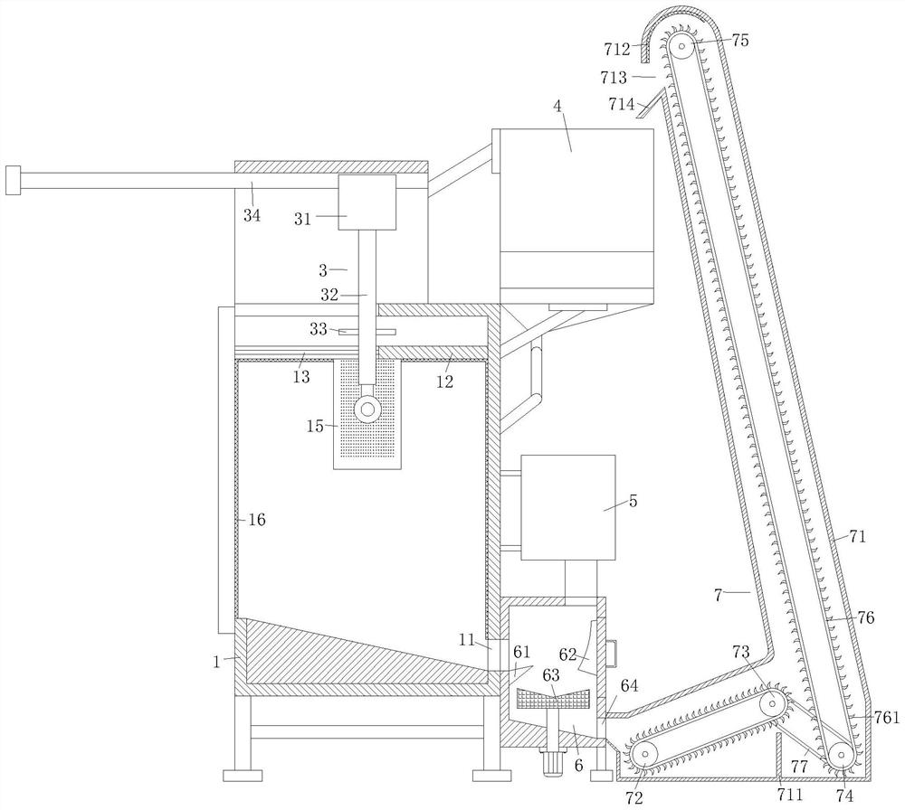
[0026] As an embodiment of the present invention, the hook assembly 3 includes a motor, a control box 31, a hook 32 and an annular plate 33, the hook assembly 3 is arranged on the top of the box body 1, and the top of the box body 1 is fixedly connected with a fixed frame, and the fixed I-shaped guide rails 34 are arranged front and rear at the center of the frame top, and the I-shaped guide rails 34 are fixedly connected with the top of the fixed frame. The control box 31 is slidingly connected with the I-shaped guide rails 34 through pulleys. 31 can realize three motion states through the motor, one is that the control box itself carries the hook 32 to enter and exit the box 1, the other is to control the lifting of the hook 32, and the third is the overall rotation of the hook 32, so as to realize the replacement of the shot blasting workpiece The top of the box body 1 is provided with a baffle plate 12, the baffle plate 12 is fixedly connected with the side walls around the...


PUM


Abstract

The invention belongs to the technical field of material surface treatment, and particularly relates to a pneumatic numerical control shot blasting machine. Comprising a box body, an impeller head, a lifting hook assembly, a feeding box, a waste treatment box, a screening box and a steel shot recovery device, the bottom wall of the box body is of a structure high in front and low in rear, the screening box is arranged on the rear side of the box body and fixedly connected with the rear wall of the box body, and a first discharging opening is formed in the part, fixedly connected with the box body, of the screening box; a wedge-shaped baffle is arranged in the screening box and located on the lower side of the first discharging port and fixedly connected with the front wall of the screening box, the bottom wall of the screening box is of a structure high in front and low in rear, a motor is arranged at the bottom of the screening box, a disc-shaped electromagnet is fixedly connected to the top of a rotating shaft of the motor, and the upper surface of the electromagnet is of an inverted-cone-shaped structure. According to the steel shot screening and recycling device, automatic screening and recycling of steel shots can be achieved, and compared with the prior art, the screening precision is higher, the maintenance frequency is effectively reduced, and the cost is saved.

Description

technical field [0001] The invention belongs to the technical field of material surface treatment, and in particular relates to a pneumatic numerical control shot blasting machine. Background technique [0002] Shot blasting equipment is firstly used to remove sand and scale on the surface of cast steel and iron castings in the foundry industry. [0003] Almost all steel castings, gray castings, malleable steel parts, ductile iron parts, etc. must be shot blasted. This is not only to remove scale and sticky sand on the surface of the casting, but also an indispensable preparation process before the quality inspection of the casting. For example, the casing of a large gas turbine must be subjected to strict shot blasting before non-destructive testing to ensure the accuracy of the testing results. reliability. In the production of general castings, shot peening cleaning is an indispensable process to find surface defects of castings such as subcutaneous pores, slag pores, s...

Claims


Application Information

Patent Timeline
Patent Type & Authority Applications(China)
IPC IPC(8): B24C1/08B24C1/10B24C9/00B03C1/30B07B15/00
CPCB24C1/08B24C1/10B24C9/006B24C9/003B24C9/00B03C1/30B07B15/00Y02P70/10
Inventor 刘会恺李宝杰
Owner 刘会恺
Why Eureka
Try Eureka