Thermoelectric conversion device and system

A technology of thermoelectric conversion devices and heat sinks, which is applied to motors, electrical components, generators/motors, etc. that apply thermal effects, and can solve problems such as increased power consumption of thermoelectric conversion devices, increased liquid flow resistance, and obstruction, so as to reduce swirl The formation of the zone, the reduction of flow resistance, and the effect of avoiding impact

Active Publication Date: 2022-03-15
SICHUAN UNIV
View PDF17 Cites 1 Cited by
  • Summary
  • Abstract
  • Description
  • Claims
  • Application Information

AI Technical Summary

Problems solved by technology

[0005] However, whether figure 1 PCB style heat sink shown, or figure 2 The plate heat exchange structure shown in the figure is equipped with a turbulence structure inside. Although the turbulence structure can enhance the heat exchange efficiency, the turbulence structure hinders the inflowing liquid and increases the flow resistance of the liquid flowing into the interior. , which increases the power consumption of the entire thermoelectric conversion device

Method used


Image

  • Thermoelectric conversion device and system
  • Thermoelectric conversion device and system
  • Thermoelectric conversion device and system

Examples


Embodiment 1

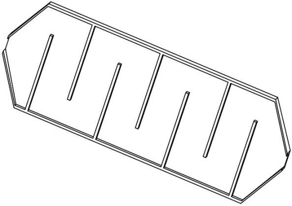
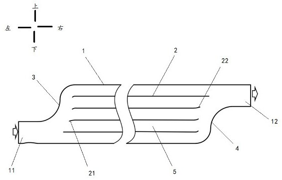
[0044] This application provides a thermoelectric conversion device, please refer to image 3 As shown, the device includes: a heat exchange heat sink shell 1, the two ends of the heat exchange heat sink shell 1 in the length direction are respectively provided with a liquid inlet 11 and a liquid outlet 12, and the heat exchange heat sink shell 1 is provided with a A plurality of rib walls 2 extending in length, and the plurality of rib walls 2 are arranged at intervals along the width direction of the heat exchange heat sink shell 1 , and a plurality of channels 5 are formed between the plurality of rib walls 2 .

[0045] In the present invention, the liquid inlet 11 and the liquid outlet 12 are located at both ends of the heat exchange heat sink shell 1 in the length direction, and the connection line between the liquid inlet 11 and the liquid outlet 12 is inclined, so that the liquid inlet The ports 11 and liquid outlets 12 are staggered, that is, the position of the liquid...

Embodiment 2

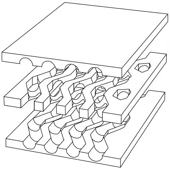
[0094] Based on the same inventive concept, another embodiment of the present application provides a thermoelectric conversion system, including: a plurality of thermoelectric conversion devices as provided in Embodiment 1 of the present invention; A thermoelectric module 6 is arranged between the conversion devices; the liquid inlets 11 of each adjacent two thermoelectric conversion devices are located on different sides, and the liquid inlet 11 of one thermoelectric conversion device in each adjacent two thermoelectric conversion devices is connected to the other thermoelectric The liquid outlets 12 of the conversion device are staggered.

[0095] In this invention, see Figure 6 As shown, the thermoelectric conversion device is stacked with the thermoelectric module 6 , and the heat dissipated by the thermoelectric conversion module is received by the thermoelectric module 6 and then converted into electrical energy.

[0096] Specifically, the thermoelectric module 6 may b...


PUM

PropertyMeasurementUnit
Angleaaaaaaaaaa

Abstract

The invention provides a thermoelectric conversion device and system, and belongs to the technical field of thermoelectric conversion. Comprising a heat exchange heat sink shell, a liquid inlet and a liquid outlet are formed in the two ends of the heat exchange heat sink shell in the length direction respectively, and a plurality of rib walls are arranged in the heat exchange heat sink shell; the end where the liquid inlet is located is provided with a first arc-shaped area, and the end where the liquid outlet is located is provided with a second arc-shaped area. The first end, close to the liquid inlet, of each rib wall is bent towards the liquid inlet, and the second end, close to the liquid outlet, of each rib wall is bent towards the liquid outlet. In the plurality of first end parts, the bending radian of the first end part far away from the liquid inlet is greater than that of the first end part close to the liquid inlet; the distance from the first end part far away from the liquid inlet to the first arc-shaped area is smaller than the distance from the first end part close to the liquid inlet to the first arc-shaped area. By using the thermoelectric conversion device and system provided by the invention, the flow resistance of the liquid can be reduced while the heat exchange uniformity and the thermoelectric conversion efficiency are improved.

Description

technical field [0001] The present application relates to the technical field of thermoelectric conversion, in particular, to a thermoelectric conversion device and system. Background technique [0002] The thermoelectric conversion technology based on thermoelectric materials is one of the effective ways to directly convert low-grade heat energy into electrical energy. Since the heat exchange process in the thermoelectric conversion device has a significant impact on the thermoelectric conversion efficiency, the current thermoelectric conversion device is equipped with There is a turbulence structure to strengthen the heat transfer process, thereby improving the efficiency of the thermoelectric conversion system. [0003] For example, see figure 1 As shown, the thermoelectric conversion device includes a printed circuit board heat sink and a thermoelectric module stacked. Each layer of the printed circuit board heat sink is formed by stacking and welding three layers of st...

Claims


Application Information

Patent Timeline
IPC IPC(8): H02N11/00H02N10/00
CPCH02N11/002H02N10/00
Inventor 谢和平夏恩通孙立成皋天一龙西亭王俊李存宝可汗莫政宇杜敏华强
Owner SICHUAN UNIV
Why Eureka
Try Eureka