Camera module and digital equipment thereof
A camera module and lens module technology, applied in installation, electromechanical devices, focusing devices, etc., to achieve balanced weight distribution, continuous and stable current, and small size
- Summary
- Abstract
- Description
- Claims
- Application Information
AI Technical Summary
Problems solved by technology
Method used
Image
Examples
Embodiment 1
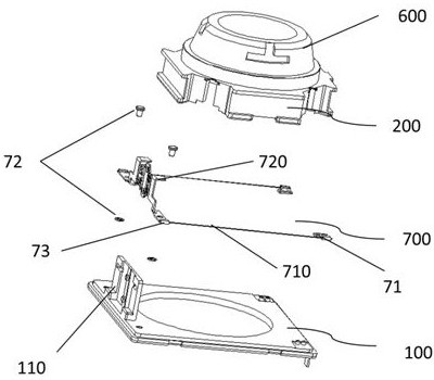
[0090] Such as Figure 1 to Figure 4 As shown, a camera module is provided in this embodiment, including:
[0091] Mobile unit 200, base 100 and at least one locking structure 700;
[0092] The moving unit 200 includes a lens module 600, and the moving unit 200 is adapted to drive the lens module 600 to move along the optical axis direction;
[0093] The base 100 is suitable for carrying the mobile unit 200;
[0094] The locking structure 700 includes a shape memory alloy part 710 and a locking part 720 , and the shape memory alloy part 710 is adapted to drive the locking part 720 to move to lock or release the mobile unit 200 .
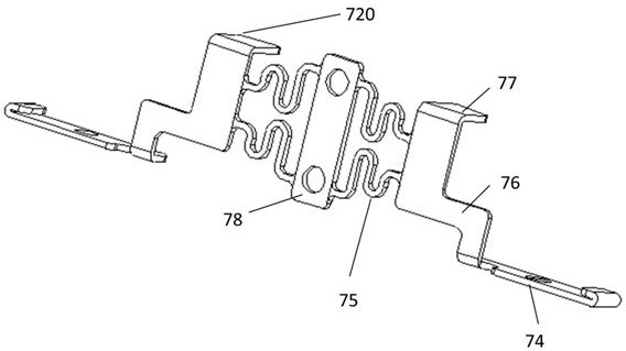
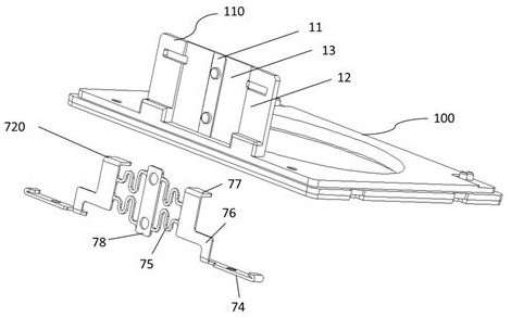
[0095] Specifically, refer to figure 2 As shown, in this embodiment, the locking part 720 further includes:
[0096] Rotary arm 74, connecting portion 76 and resilient portion 75;
[0097] Both sides of the rotating arm 74 are respectively connected to the shape memory alloy part 710 and the connecting part 76, and the connecting part 76 is pro...
Embodiment 2
[0129] Such as Figure 6 to Figure 9 As shown, a camera module is provided in this embodiment, including:
[0130] Mobile unit 200, base 100 and at least one locking structure 700;
[0131] The moving unit 200 includes a lens module 600, and the moving unit 200 is adapted to drive the lens module 600 to move along the optical axis direction;
[0132] The base 100 is suitable for carrying the mobile unit 200;
[0133] The locking structure 700 includes a shape memory alloy part 710 and a locking part 720 , and the shape memory alloy part 710 is adapted to drive the locking part 720 to move to lock or release the mobile unit 200 .
[0134] Specifically, refer to Figure 7 to Figure 8 As shown, in this embodiment, the locking part 720 further includes:
[0135] Rotary arm 74, connecting portion 76 and resilient portion 75;
[0136] Both sides of the rotating arm 74 are respectively connected to the shape memory alloy part 710 and the connecting part 76, and the connecting pa...
Embodiment 3
[0169] In addition to the structure of the first embodiment or / and the second embodiment, the camera module provided in this embodiment also includes the mirror ring bearing part and the motion support part. The mirror ring bearing part is used to ensure the stable movement and waterproof and dustproof of the lens, and the moving supporting part is used to realize the stable electrical connection in the camera module when the moving assembly moves during the focusing and zooming process.
[0170] This embodiment provides a camera module, refer to Figure 5 or Figure 11 As shown, in this embodiment, the camera module shown includes a base 100, a mobile unit 200 supported by the base 100, an iron shell assembly 300 covering and protecting the mobile unit 200, which is loaded by the mobile unit 200, and placed on the iron The telescopic lens unit 600 in the shell assembly 300 and the mirror ring 500 set on the top of the lens unit. Preferably, the present embodiment provides t...
PUM
 Abstract
Description
Claims
Application Information
 - Generate Ideas
- Intellectual Property
- Life Sciences
- Materials
- Tech Scout
- Unparalleled Data Quality
- Higher Quality Content
- 60% Fewer Hallucinations
Browse by: Latest US Patents, China's latest patents, Technical Efficacy Thesaurus, Application Domain, Technology Topic, Popular Technical Reports.
© 2025 PatSnap. All rights reserved.Legal|Privacy policy|Modern Slavery Act Transparency Statement|Sitemap|About US| Contact US: help@patsnap.com


