Ultrasonic phased array defect imaging method based on F-DMAS and pseudo color

A F-DMAS, ultrasonic phased array technology, applied in the direction of material analysis, image enhancement, image analysis, etc. using sonic/ultrasonic/infrasonic waves, can solve problems such as dependence, difficulty in identifying defects in false color images, and achieve the advantage of detection capabilities , the advantage of expression effect, the effect of improving expression effect

Active Publication Date: 2022-03-15
CENT SOUTH UNIV
View PDF4 Cites 0 Cited by
  • Summary
  • Abstract
  • Description
  • Claims
  • Application Information

AI Technical Summary

Problems solved by technology

In addition, the current ultrasonic pseudo-color imaging does not combine the F-DMAS method to suppress incoherent noise, and the defect information in the imaging results still depends on the subjective judgment of professionals, which makes it still difficult to identify defects from pseudo-color images

Method used


Image

  • Ultrasonic phased array defect imaging method based on F-DMAS and pseudo color
  • Ultrasonic phased array defect imaging method based on F-DMAS and pseudo color
  • Ultrasonic phased array defect imaging method based on F-DMAS and pseudo color

Examples


Embodiment 1

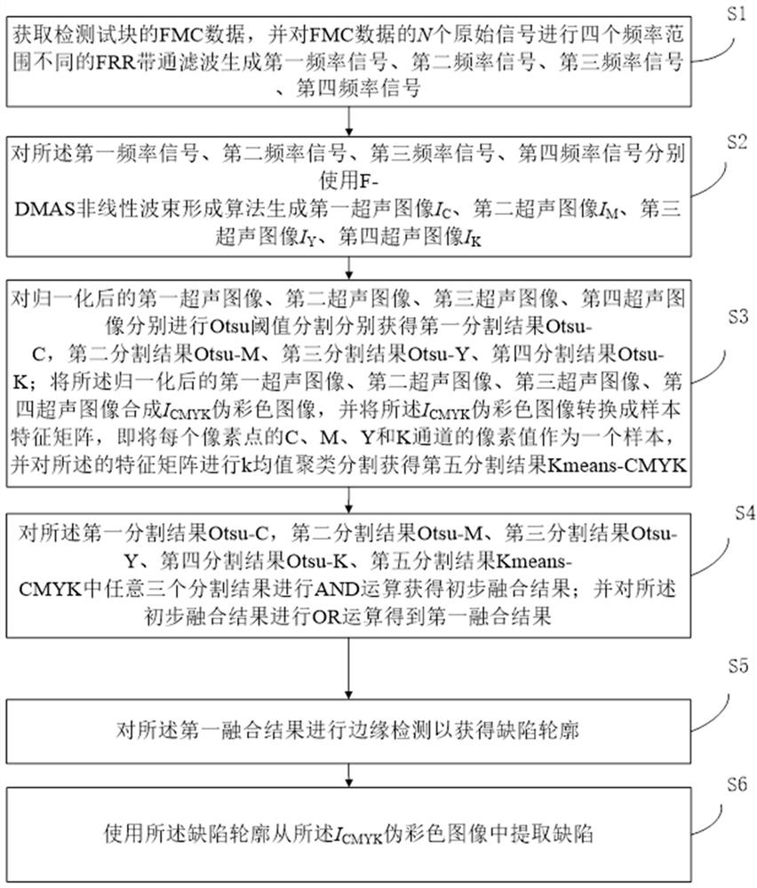
[0048] refer to figure 1 , the present embodiment discloses an ultrasonic phased array defect imaging method based on F-DMAS and pseudo-color, which includes the following steps:

[0049] S1, obtain the FMC data of the detection test block, and perform four FRR bandpass filters with different frequency ranges on the N original signals of the FMC data to generate a first frequency signal, a second frequency signal, a third frequency signal, and a fourth frequency signal ;

[0050] The first frequency signal is a low frequency signal, the second frequency signal is an intermediate frequency signal, the third frequency signal is a high frequency signal, and the fourth frequency signal is a full frequency signal. Without loss of generality, the first frequency is cyan, and the second frequency is magenta. Red, the third frequency is yellow, and the fourth frequency is black.

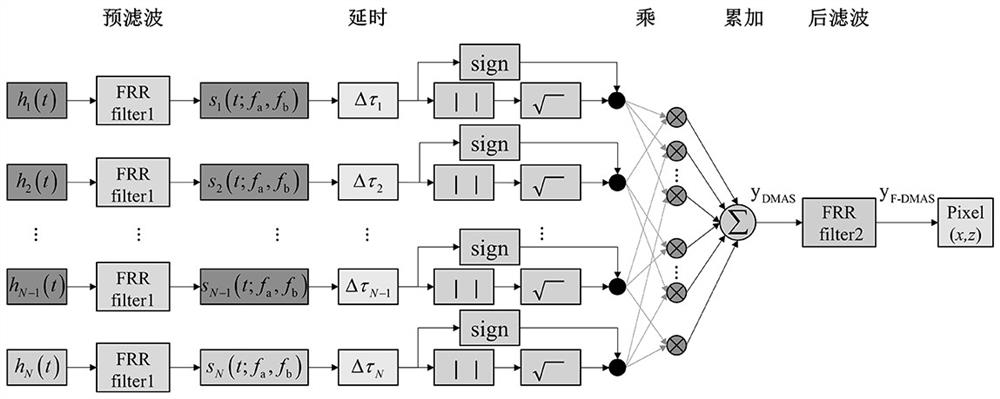
[0051] Schematic diagram of the F-DMAS imaging algorithm as shown in figure 2 shown. Suppose the pha...

Embodiment 2

[0095] refer to Figure 10 , this embodiment discloses a strong attenuation material defect detection device based on F-DMAS and pseudo-color ultrasonic phased array defect imaging detection device, which includes the following units:

[0096] The band-pass filter extraction unit is used to detect the FMC data of the test block, and perform four FRR band-pass filters with different frequency ranges on the N original signals of the FMC data to generate a first frequency signal, a second frequency signal, and a first frequency signal. Three frequency signals, fourth frequency signals; filter delay multiplication and accumulation nonlinear beamforming ultrasonic imaging unit, used to generate first ultrasonic waves for the first frequency signal, second frequency signal, third frequency signal, and fourth frequency signal respectively image I C , second ultrasound image I M , the third ultrasound image I Y , the fourth ultrasound image I K ;

[0097] Segmentation unit, f...


PUM

PropertyMeasurementUnit
diameteraaaaaaaaaa
diameteraaaaaaaaaa

Abstract

The invention provides an ultrasonic phased array defect imaging method based on filtering delay multiply-accumulate (F-DMAS) and CMYK pseudo-color, and introduces an automatic color image segmentation technology to detect defects in a strong attenuation material. The method comprises the following steps: firstly, performing post-processing on full matrix capture (FMC) data by adopting an F-DMAS algorithm; then, the influence of frequency component selection on F-DMAS imaging is analyzed, and the influence of attenuation on defect echoes is discussed. Thirdly, separating frequency components of the signals by using a pseudo-color technology, and generating a color image with frequency and intensity information, so as to improve the information amount of the ultrasonic image and the expression effect of defects; and finally, performing color image segmentation and edge detection on a pseudo-color imaging result to realize automatic extraction of a defect contour. Compared with a linear full-focusing imaging method, the method provided by the invention has remarkable advantages in the aspects of signal-to-noise ratio, detection capability, expression effect and the like of defects.

Description

technical field [0001] The invention relates to the technical field of ultrasonic detection, in particular to an ultrasonic phased array imaging method for defects in strong attenuation materials based on F-DMAS and false color. Background technique [0002] Ultrasonic phased array imaging is widely used in the field of industrial and medical non-destructive testing. However, when ultrasonic waves propagate in strong attenuating materials such as coarse grains or particle composites, severe energy loss will result due to scattering attenuation and absorption attenuation. Internal defects in these strongly attenuating materials are difficult to detect with traditional ultrasonic phased array imaging methods. Because the defect echo signal will be severely attenuated in strong attenuation materials, the imaging results may be submerged in electrical noise or structural noise, resulting in a low signal-to-noise ratio, which seriously affects the effective identification of def...

Claims


Application Information

Patent Timeline
Patent Type & Authority Applications(China)
IPC IPC(8): G06T7/00G06T7/12G06T7/13G06T7/136G06T5/10G06T5/30G01N29/44
CPCG06T7/0004G06T7/12G06T7/13G06T7/136G06T5/10G06T5/30G01N29/4472G06T2207/10024G06T2207/10132G06T2207/20056
Inventor 李雄兵禹利达李海宁宋永锋杨占锋
Owner CENT SOUTH UNIV
Why Eureka
Try Eureka