Container conveying system capable of achieving unmanned unloading

A conveying system and container technology, applied in the field of container conveying system, can solve the problems of cargo squeeze vibration, cargo damage, damage, etc., and achieve the effect of increasing stability

Active Publication Date: 2022-03-15
启东荻捷工业成套设备有限公司
View PDF8 Cites 0 Cited by
  • Summary
  • Abstract
  • Description
  • Claims
  • Application Information

AI Technical Summary

Problems solved by technology

[0003] Some solutions have also been proposed for the existing technology of unloading cargo on existing container trucks. The Chinese utility model patent with the publication number CN202896358U discloses a low-flat container semi-trailer dump truck. The container is extended as a whole to achieve the purpose of unloading. This method of unloading can only be used for specific goods. The above method for ordinary goods will cause damage to the goods; the existing unloading for containers will also be transmitted through external conveyor belts, etc. Parts cooperate to unload the cargo
[0004] The above-mentioned prior art still has the following problems when loading goods in the truck container: 1. When the truck container is extended as a whole, it will cause the goods to squeeze and vibrate and be damaged, and the volume of the container is generally large, and the container is located near the front of the truck. One side of the container cannot be unloaded; unloading through the external transmission part requires manual cooperation to place the goods on the transmission part, and when the goods are transported to the outer end of the container along the transmission part, it is also necessary to manually remove the goods from the transmission part, thus The amount of manual labor is large, and there is a danger of the goods falling from the transmission parts and causing damage

Method used


Image

  • Container conveying system capable of achieving unmanned unloading
  • Container conveying system capable of achieving unmanned unloading
  • Container conveying system capable of achieving unmanned unloading

Examples


Embodiment Construction

[0034] The embodiments of the present invention are described in detail below; the embodiments described below are exemplary, are only used to explain the present invention, and cannot be interpreted as limitations of the present invention; if no specific techniques or conditions are indicated in the embodiments, according to the technical field The techniques or conditions described in the literature or in accordance with the product instructions.

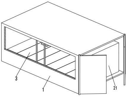
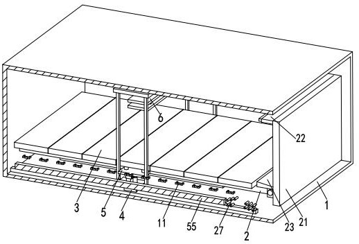
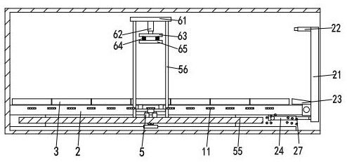
[0035] refer to Figure 1 to Figure 3 , Figure 8 , a container conveying system that can be unmanned unloading, including a container body 1, a support base 2, a mounting plate 3, an electric slider 4 and a jacking mechanism 5, the container body 1 is a box structure, and the container body 1 The right end is provided with an opening and closing door, and the lower side wall of the container body 1 is equipped with a support base 2, and the upper side of the support base 2 is evenly provided with a mounting plate 3 along its len...


PUM


Abstract

The invention relates to the technical field of vehicle unloading, in particular to an unmanned unloading container conveying system which comprises a container body, a supporting base, lapping plates, electric sliding blocks and a jacking and extending mechanism, the supporting base is installed on the lower side wall in the container body, and the lapping plates are evenly arranged on the upper side face of the supporting base in the length direction of the supporting base; two electric sliding blocks are arranged on the lower side wall in the container body, the two electric sliding blocks are symmetrically distributed on the front side and the rear side of the supporting base, and each electric sliding block is provided with a jacking and extending mechanism; according to the conveying system, the design integrated with a truck container is adopted, cargoes in the container can be sequentially unloaded from right to left, the cargoes can be controlled to automatically incline and slide onto the overturning plate when the cargoes are unloaded, the cargoes are overturned to the outer side of the container through the overturning plate, and the unloading action of the cargoes is facilitated.

Description

technical field [0001] The invention relates to the technical field of vehicle unloading, in particular to a container conveying system capable of unmanned unloading. Background technique [0002] Large container trucks can transport a large amount of goods and ensure the integrity of the goods. Although container trucks have many advantages, it is more difficult for container trucks to unload. [0003] Some solutions have also been proposed for the existing technology of unloading cargo on existing container trucks. The Chinese utility model patent with the publication number CN202896358U discloses a low-flat container semi-trailer dump truck. The container is extended as a whole to achieve the purpose of unloading. This method of unloading can only be used for specific goods. The above method for ordinary goods will cause damage to the goods; the existing unloading for containers will also be transmitted through external conveyor belts, etc. The components cooperate to u...

Claims


Application Information

Patent Timeline
Patent Type & Authority Applications(China)
IPC IPC(8): B65G67/24B65G69/00
CPCB65G67/24B65G69/00
Inventor 王应龙方勇
Owner 启东荻捷工业成套设备有限公司
Why Eureka
Try Eureka