
Crushed hair recovery equipment for brush processing

A technology for recycling equipment and brushes, which is applied in the field of broken hair recovery equipment for brush processing, can solve the problems affecting the normal recovery of broken hair and the impact of brush processing efficiency, and achieves the effects of good linkage, improved processing efficiency and simple operation.

Inactive Publication Date: 2022-03-15
安徽省潜山县团结制刷有限公司
View PDF0 Cites 0 Cited by
  • Summary
  • Abstract
  • Description
  • Claims
  • Application Information

AI Technical Summary

Problems solved by technology

The hair removal device in the prior art often directly sucks the hair into the device through the fan. When taking out the hair in the device, it is necessary to shut down the device first, which affects the normal recovery of the hair and causes the processing efficiency of the brush to be affected. influences

Method used


Image

  • Crushed hair recovery equipment for brush processing
  • Crushed hair recovery equipment for brush processing
  • Crushed hair recovery equipment for brush processing

Examples


Embodiment 1

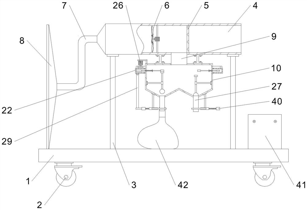
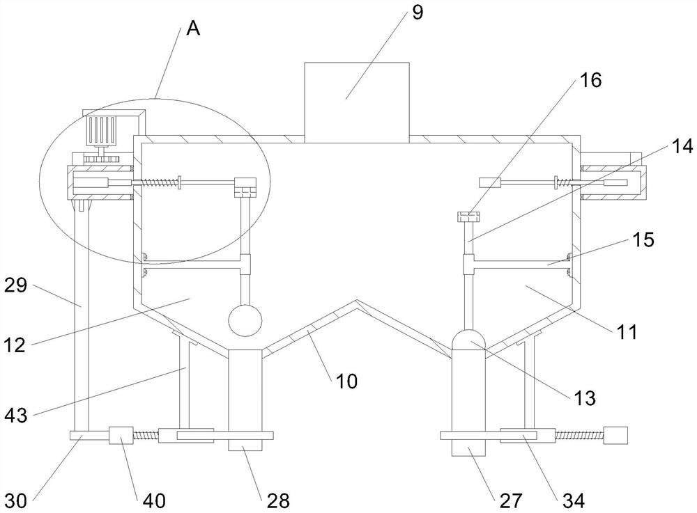
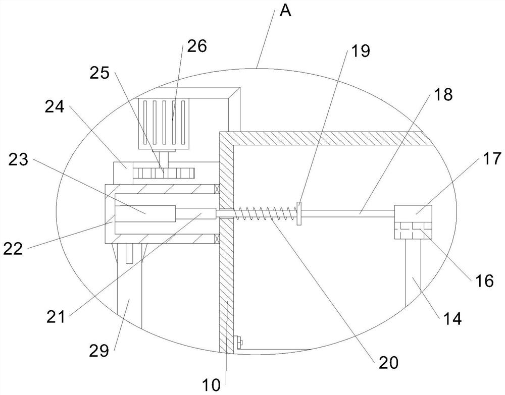
[0030] In this embodiment, as shown in Figures 1-6, a broken hair recovery device for brush processing includes a bottom plate 1, and a roller 2 is installed at the bottom of the bottom plate 1. The top of the bottom plate 1 is fixed with a cylinder 4 through the legs 3, the inner wall of the cylinder 4 is fixed with a filter plate 5, and one end of the cylinder 4 is connected with a suction hood 8 through a hose 7, and the suction hood 8 is fixed with the bottom plate 1 A fan 6 is installed on the inner wall of the cylinder 4 corresponding to the position between the hose 7 and the filter plate 5, and the bottom wall of the cylinder 4 is located on one side of the filter plate 5 and is connected with a silo 10 through a drop pipe 9. The silo 10 Divided into cavity one 11 and cavity two 12, the bottom wall of cavity one 11 is connected with connecting tube one 27, the bottom wall of cavity two 12 is connected with connecting tube two 28, cavity one 11 and cavity two 12 are conn...

Embodiment 2

[0033] On the basis of Embodiment 1, the bottom ends of cavity one 11 and cavity two 12 are provided with a clamping mechanism for clamping the plastic bag 42 through the vertical rod 43, and the rotating shell 22 is correspondingly connected with the two clamping mechanisms. The clamping mechanism includes a housing 31 fixed on the bottom of the vertical rod 43. The front and rear side walls of the housing 31 are connected with push rods 32 slidingly through them. The outer ends of the two push rods 32 are fixed with clamp rods 34. Bar 32 corresponds to the position between the housing 31 and the clamping rod 34 and is sleeved with a spring 2 33, and the inner ends of the two clamping rods 34 are fixed with clamping plates 35, and the inner ends of the clamping plates 35 are fixed with rubber pads. The positions of the two push rods 32 on the inner wall of the housing 31 are equipped with fixed pulleys 36, and the inner ends of the two push rods 32 are fixed with stay ropes 37...


PUM


Abstract

The invention relates to the field of brush processing, in particular to broken hair recovery equipment for brush processing, which comprises a cylinder, the bottom wall of the cylinder is communicated with a stock bin through a blanking pipe, the stock bin is divided into a cavity I and a cavity II, the bottom wall of the cavity I is communicated with a connecting pipe I, and the bottom wall of the cavity II is communicated with a connecting pipe II. Sealing mechanisms are arranged on the cavity I and the cavity II; a driving part, a sealing mechanism, a clamping mechanism and the like are additionally arranged, a second connecting pipe is sleeved with another new plastic bag, the driving part is controlled to drive a rotating shell to rotate, a first extrusion block on the rotating shell extrudes a round block on one side of a second cavity, a sealing ball in the second cavity moves upwards, and the second connecting pipe is unblocked; in the process, the sealing ball in the first cavity moves downwards to block the first connecting pipe, then the plastic bag on the first connecting pipe can be taken down, equipment does not need to be shut down when the broken hair is taken out, normal recovery of the broken hair is not affected, and the working efficiency is improved.

Description

technical field [0001] The invention relates to the technical field of brush processing, in particular to a broken hair recovery device for brush processing. Background technique [0002] The brush is a traditional labor tool that originated in China. The hair brush is a utility model of the ancient Han working people in production practice. During the molding process of the existing brushes, the bristles need to be trimmed and leveled, and the mixed broken hairs in the bristles should be removed. [0003] During the process of trimming the bristles and removing the fine hairs, the resulting fine hairs fall into the surrounding environment. The hair removal device in the prior art often directly sucks the hair into the device through the fan. When taking out the hair in the device, it is necessary to shut down the device first, which affects the normal recovery of the hair and causes the processing efficiency of the brush to be affected. influences. For this reason, we h...

Claims


Application Information

Patent Timeline
IPC IPC(8): B08B5/04B08B13/00A46D9/02
CPCB08B5/04B08B13/00A46D9/02
Inventor 徐团结华月年徐仪琼
Owner 安徽省潜山县团结制刷有限公司
Learn More