Hydraulic braking system, hydraulic braking control method and related equipment

A technology of hydraulic braking and control methods, which is applied in the direction of braking transmission, brakes, transportation and packaging, etc., can solve the problems of inaccurate braking, braking delay, piston movement delay, etc., and achieve fast braking response speed, The effect of high braking precision

Active Publication Date: 2022-03-11
武汉元丰汽车电控系统股份有限公司 +1
View PDF5 Cites 0 Cited by
  • Summary
  • Abstract
  • Description
  • Claims
  • Application Information

AI Technical Summary

Problems solved by technology

In the existing technology, the pressure of the brake fluid is controlled by the control system, and the brake fluid with a predetermined pressure is injected into the front end of the brake master cylinder. The brake fluid completes the braking action, but when there are multiple pistons, the multiple pistons are usually connected in series, and the motions of the pistons are coupled with each other, and the movement of the subsequent pistons will be delayed, resulting in braking delay and Inaccurate braking and other phenomena occur, affecting the user's driving experience

Method used


Image

  • Hydraulic braking system, hydraulic braking control method and related equipment
  • Hydraulic braking system, hydraulic braking control method and related equipment
  • Hydraulic braking system, hydraulic braking control method and related equipment

Examples


Embodiment Construction

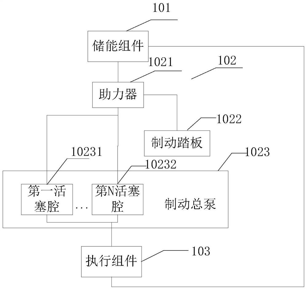
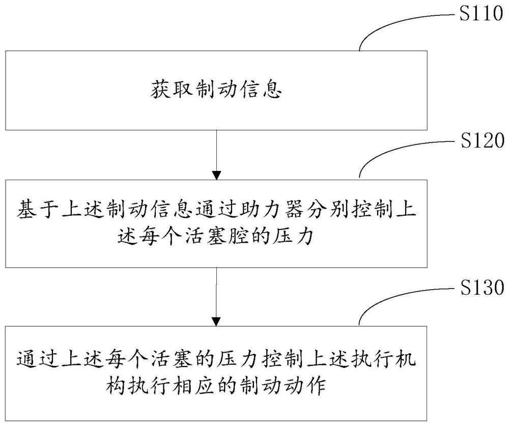
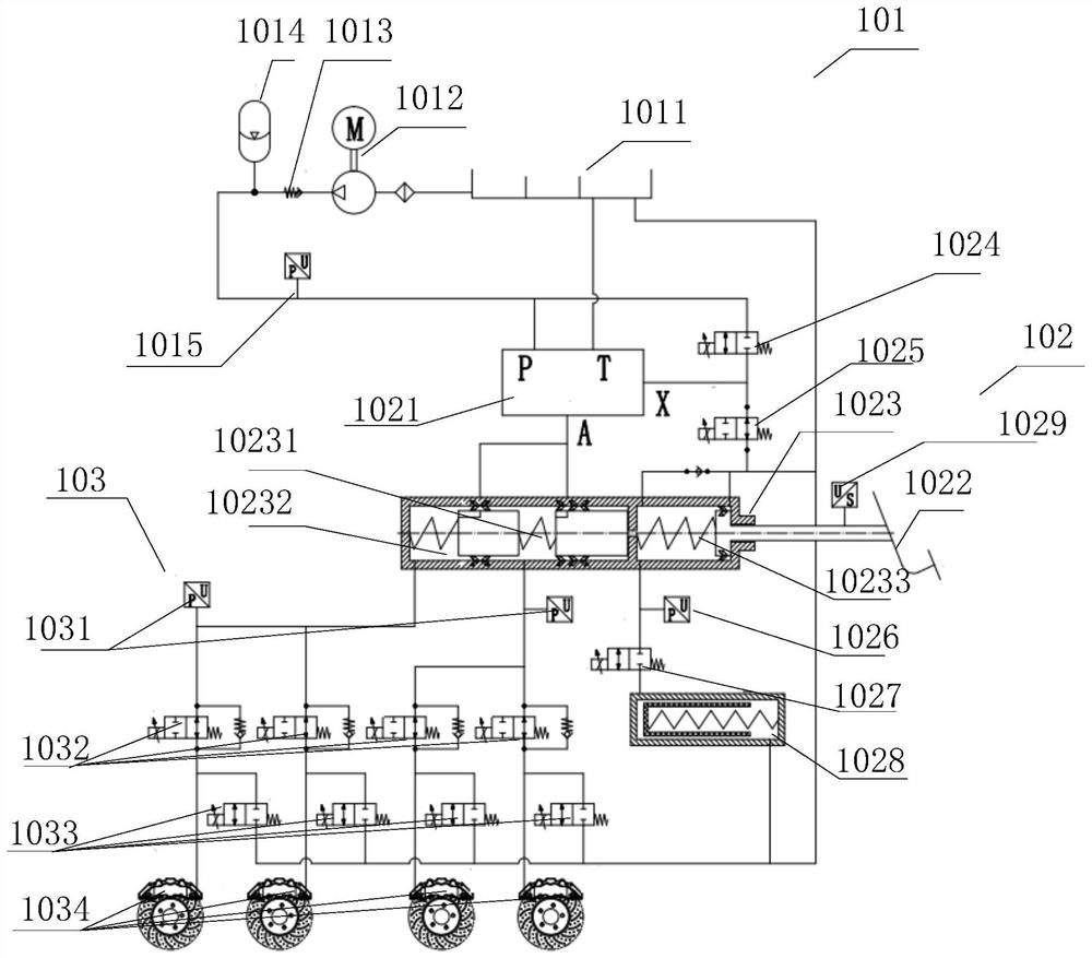
[0046] The embodiment of the present application provides a hydraulic brake control method and related equipment. In this embodiment, high-pressure brake fluid is injected into each piston chamber of the brake master cylinder respectively. At the front end, the hydraulic braking system has higher braking precision and faster braking speed.

[0047] The terms "first", "second", "third", "fourth", etc. (if any) in the specification and claims of the present application and the above drawings are used to distinguish similar objects, and not necessarily Used to describe a specific sequence or sequence. It is to be understood that the terms so used are interchangeable under appropriate circumstances such that the embodiments described herein can be practiced in sequences other than those illustrated or described herein. Furthermore, the terms "comprising" and "having", as well as any variations thereof, are intended to cover a non-exclusive inclusion, for example, a process, metho...


PUM


Abstract

The invention discloses a hydraulic brake control system, a hydraulic control method and related equipment. The system comprises an energy storage assembly, a control assembly and an execution assembly. The control assembly comprises boosters, a brake master cylinder and a brake pedal, the brake master cylinder comprises at least two piston cavities, the boosters are connected to the piston cavities respectively, and the boosters are used for controlling the pressure of the piston cavities according to the displacement of the brake pedal so as to send out a brake instruction; the execution assembly is used for executing the braking action corresponding to the control instruction sent by the control assembly. The booster is connected with each piston cavity of the brake master cylinder, the pressure of each piston cavity can be directly controlled through the displacement of the brake pedal, the execution assembly completes the braking action based on the pressure, the braking action is faster, the pistons do not move in the cavities, and complete decoupling of multi-piston movement is achieved.

Description

technical field [0001] This specification relates to the field of vehicle braking, and more specifically, the present invention relates to a hydraulic braking system, a hydraulic braking control method and related equipment. Background technique [0002] The hydraulic braking system is a commonly used braking system for current vehicles. It uses high-pressure brake fluid to pass through the brake wheel cylinder to complete the deceleration or braking of the vehicle. In the existing technology, the pressure of the brake fluid is controlled by the control system, and the brake fluid with a predetermined pressure is injected into the front end of the brake master cylinder. The brake fluid completes the braking action, but when there are multiple pistons, the multiple pistons are usually connected in series, and the motions of the pistons are coupled with each other, and the movement of the subsequent pistons will be delayed, resulting in braking delay and Inaccurate braking an...

Claims


Application Information

Patent Timeline
Patent Type & Authority Applications(China)
IPC IPC(8): B60T13/68B60T13/74
CPCB60T13/686B60T13/745
Inventor 童幸源王佳罗勇温斌王培利刘帅
Owner 武汉元丰汽车电控系统股份有限公司
Why Eureka
Try Eureka