
Circuit board

A circuit board, differential technology, applied in circuit devices, printed circuits, printed circuit components, etc., can solve the problems of discontinuous impedance at the connection between the connector and the circuit board, large differential signal line loss, etc., to optimize impedance continuity. , the effect of reducing differential reflection and improving quality

Pending Publication Date: 2022-03-04
中汽创智科技有限公司
View PDF3 Cites 0 Cited by
  • Summary
  • Abstract
  • Description
  • Claims
  • Application Information

AI Technical Summary

Problems solved by technology

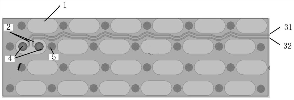
[0005] In order to solve the problems of the prior art, the embodiment of the present application provides a circuit board technical solution, which is used to solve the impedance discontinuity at the connection between the connector and the circuit board and the projection of the connector on the circuit board existing in the prior art. In the area, the differential signal can only be tightly coupled out of the line, resulting in large line loss and other problems. The technical solution is as follows:

Method used


Image

  • Circuit board
  • Circuit board
  • Circuit board

Examples


Embodiment Construction

[0037] The following will clearly and completely describe the technical solutions in the embodiments of the application with reference to the drawings in the embodiments of the application. Apparently, the described embodiments are only some of the embodiments of the application, not all of them. Based on the embodiments in the present application, all other embodiments obtained by persons of ordinary skill in the art without making creative efforts belong to the protection scope of the present application.

[0038] It should be noted that the terms "first" and "second" in the specification and claims of the present application and the above drawings are used to distinguish similar objects, but not necessarily used to describe a specific order or sequence. It is to be understood that the data so used are interchangeable under appropriate circumstances such that the embodiments of the application described herein can be practiced in sequences other than those illustrated or desc...


PUM


Abstract

The invention discloses a circuit board which comprises a plurality of rows of pin units. The single-row pin unit is internally provided with anti-pad areas and backflow ground holes which are arranged in a staggered manner; a pair of signal holes arranged in the anti-pad area; the differential wires are distributed in a snakelike manner and are connected with the pair of signal holes in a one-to-one correspondence manner; the differential wires are arranged between two adjacent rows of pin units; the snakelike bulge on the differential wire is close to the backflow ground hole at the periphery of the snakelike bulge and is far away from the signal hole at the periphery of the snakelike bulge; the impedance adjusting part is arranged on the side, connected with the signal hole, of the differential wire and located in the anti-pad area. According to the invention, impedance continuity of high-speed signals at the joint of the circuit board and the connector can be improved, and insertion loss and differential reflection are reduced at the same time.

Description

technical field [0001] The application relates to the field of circuit board design of communication products, in particular to a circuit board. Background technique [0002] In high-speed system design, the primary goal is the continuous impedance of the signal transmission path, so as to ensure the minimum signal reflection (return loss), and the pins of the high-speed backplane connector are restricted by the structure of the hole plate, which must exist in the high-speed signal transmission channel. An impedance discontinuity point, the pin distribution of the connector will also bring common mode inductance and parasitic capacitance, which will affect the signal transmission amplitude (insertion loss) and differential pair skew. In addition, such as Amphenol's 6pair XCede HD connector, due to Due to the limitation of the distance between two adjacent rows of connector pins, in the projection area of ​​the connector on the circuit board (PCB), the differential signal can...

Claims


Application Information

Patent Timeline
IPC IPC(8): H05K1/02
CPCH05K1/0245H05K1/025H05K1/0216H05K1/02
Inventor 李丰军周剑光
Owner 中汽创智科技有限公司
Learn More