
Energy storage system

A technology of energy storage system and temperature control system, applied in the field of energy storage system, can solve the problems of bulky, poor applicability, and low cooling efficiency

Pending Publication Date: 2022-03-04
HUAWEI DIGITAL POWER TECH CO LTD
View PDF0 Cites 0 Cited by
  • Summary
  • Abstract
  • Description
  • Claims
  • Application Information

AI Technical Summary

Problems solved by technology

The inventors of the present application found that in the process of research and practice, in the prior art, the air cooling device uses air circulation to cool the energy storage system, which usually requires a large air supply space (that is, the air duct), which makes the use of The volume of the energy storage system for cooling by the air cooling device is too large, and the air cannot directly contact the cells in the battery, resulting in low cooling efficiency
At the same time, because the air in the air cooling device has a different air supply distance from the air inlet to each battery (or battery pack) in the energy storage system, the temperature difference between the batteries in the energy storage system is large
However, compared with air-cooled devices, water-cooled devices have a better cooling effect, but the layout cost of water-cooled devices is usually higher, and the medium used for cooling in the pipeline is usually a conductive liquid, and the energy storage system has low safety and poor applicability

Method used


Image

  • Energy storage system
  • Energy storage system
  • Energy storage system

Examples


Embodiment Construction

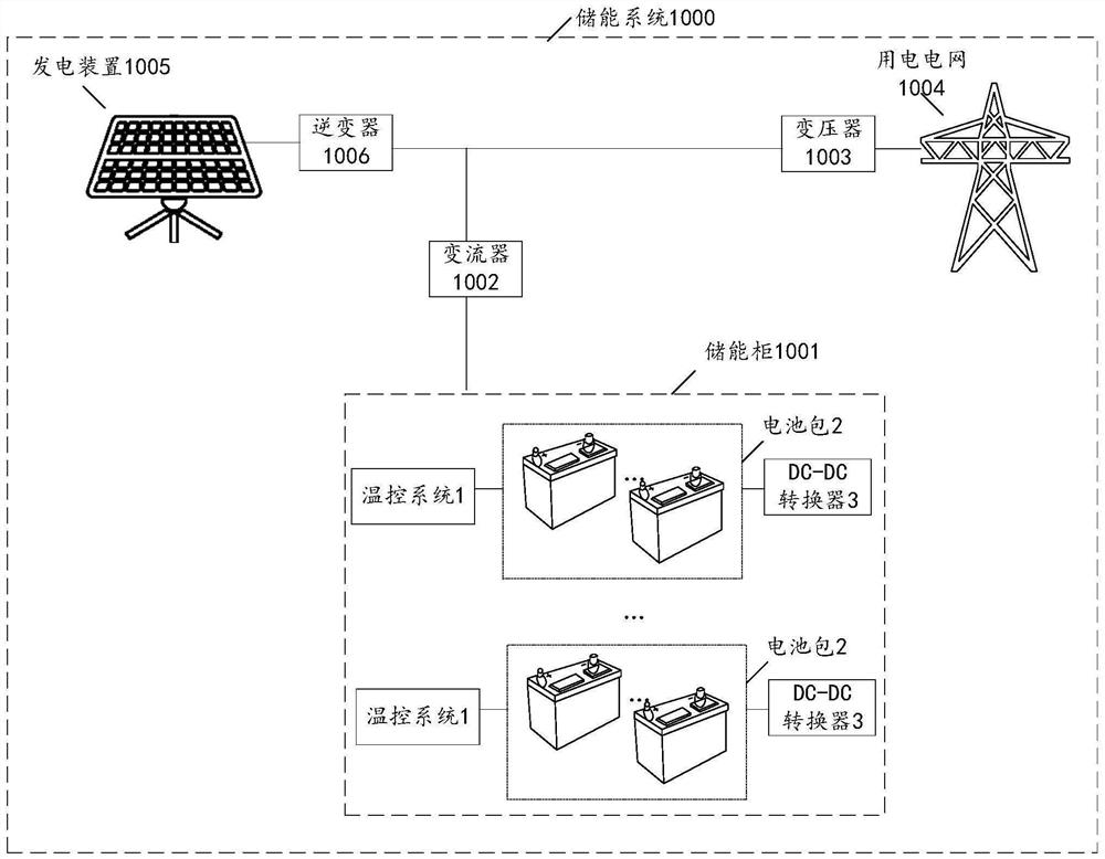
[0048] The energy storage system provided herein may be applied to the field of new energy smart piconet, or transmission and distribution areas of new energy (photovoltaic or wind field and grid network field), power generation optical storage (such as domestic appliances (such as refrigerators , air conditioning) or power supply), or the air storage power generation, or the field power converter (e.g., converting DC power of high voltage alternating current) and other applications, and in particular may be determined according to the actual application scenario, which is not limit. The energy storage system provided herein may be adapted to different application scenarios, such as scenarios glows power, wind power energy storage application scenario, or other scenario storage pure power storage scenarios, the following will optical storage energy supply scenario as an example, the following will not repeat them.

[0049] Please refer to figure 1 , figure 1 Application scenario i...


PUM


Abstract

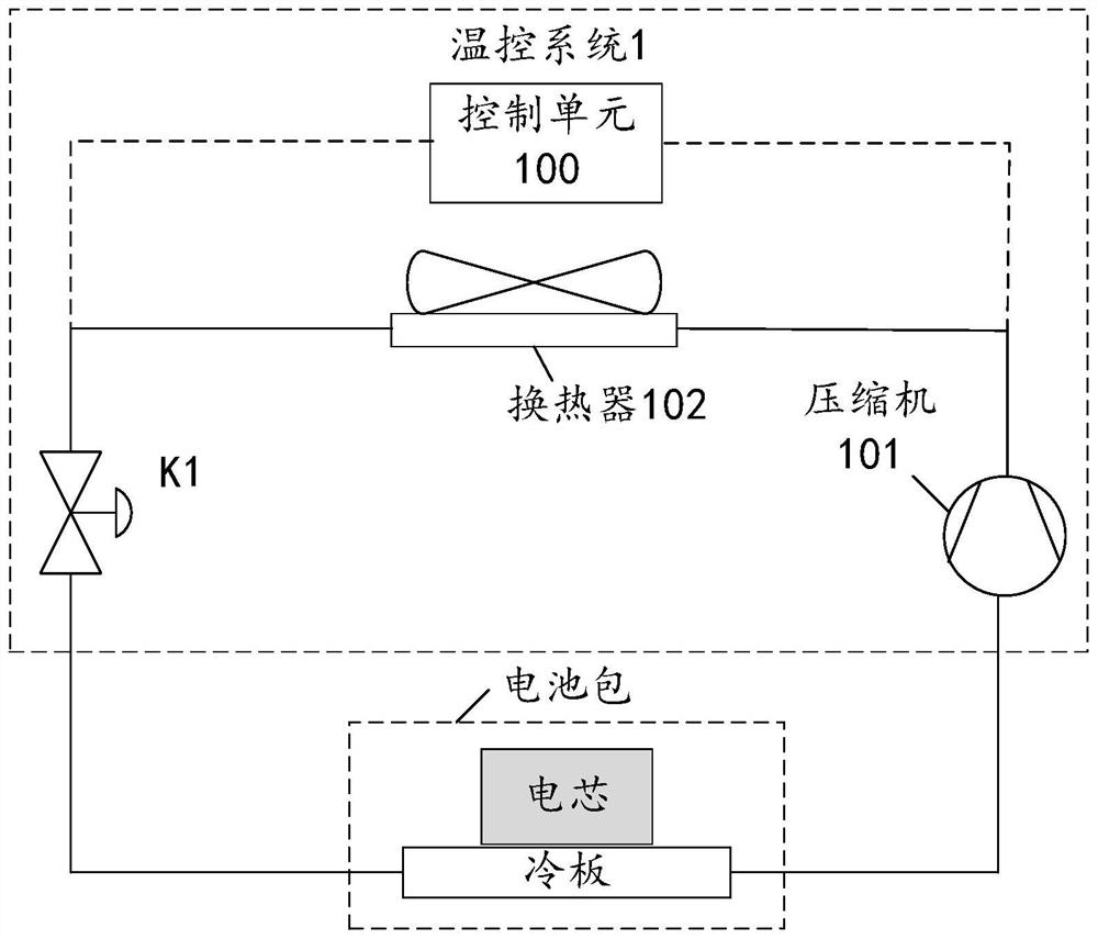
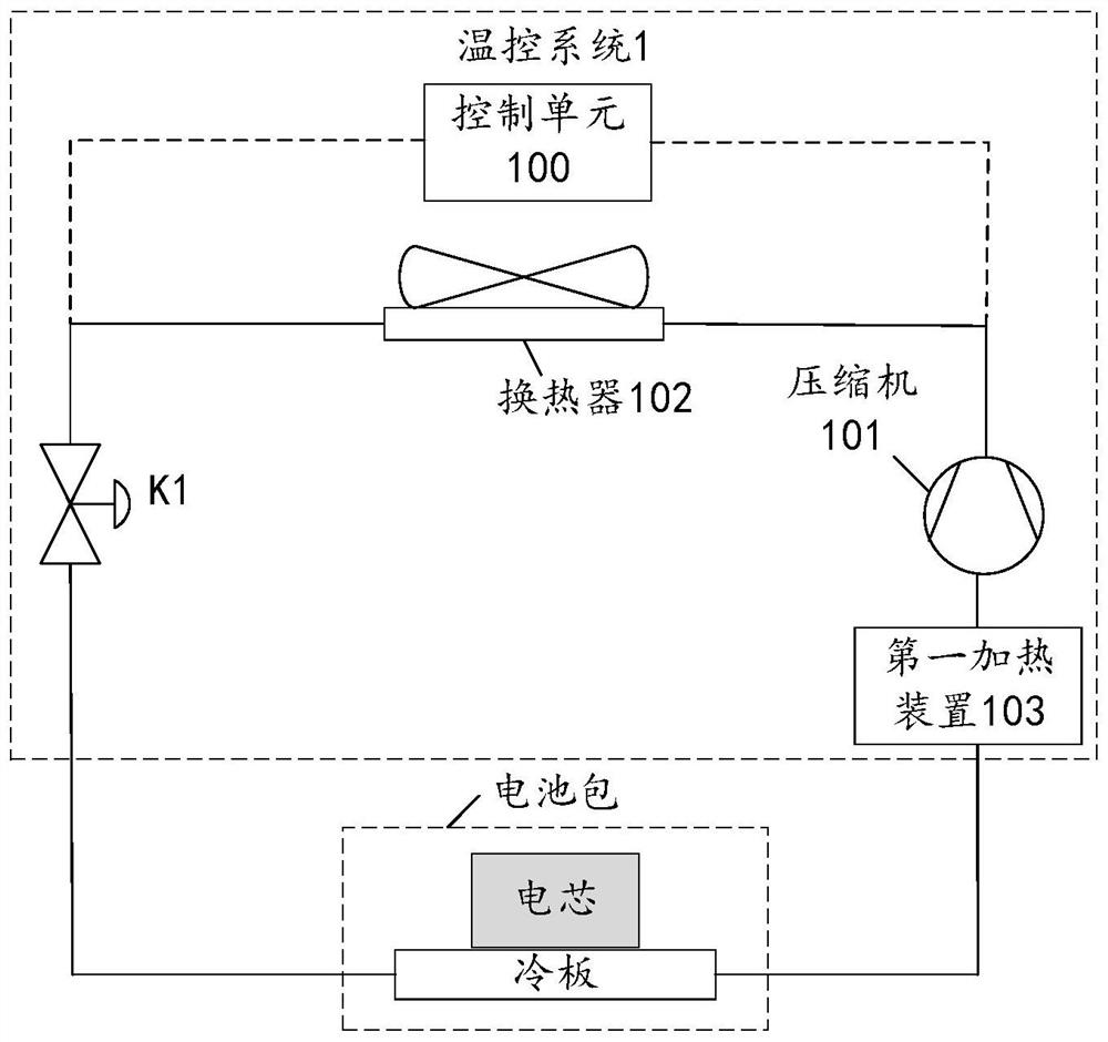
The invention provides an energy storage system which comprises at least one battery pack and a temperature control system, the battery pack comprises a cold plate and a battery cell, the cold plate is in contact with the battery cell to transfer heat energy, and the temperature control system comprises a control unit, a compressor, a heat exchanger and at least one first control valve; the control unit is used for controlling the compressor to act to compress the temperature control medium through the compressor to obtain the temperature control medium flowing to the heat exchanger when the battery cell temperature of the battery pack is larger than or equal to a first temperature threshold value, and controlling the opening degree of the first control valve to control the temperature control medium to flow into a cold plate in the battery pack to exchange heat with a battery cell so as to reduce the battery cell temperature. By the adoption of the energy storage system, the temperature of the temperature control medium can be controlled, the temperature control medium flows through the cold plate to transfer heat with the battery cell, the size of the energy storage system is reduced, the temperature control cost is reduced, and the safety of the system is improved.

Description

Technical field [0001] The present application relates to the field of power electronics, in particular, it relates to an energy storage system. Background technique [0002] In the field of power electronics technology in order to protect the power storage system components, increase battery life in the energy storage system, the temperature control member need to reduce battery energy storage system operating temperature. In a common energy storage system, is usually carried out by air cooling or water cooling apparatus. The inventors of the present application found during research and practice in the prior art, air-cooled by the air circulating means to cool the energy storage system, typically require a large blowing space (i.e., the duct), which makes use of volume of air energy storage system to cool the apparatus is too large, and the air can not be in direct contact with the battery cell, resulting in lower cooling efficiency. Meanwhile, since the ventilation unit from t...

Claims


Application Information

Patent Timeline
Patent Type & Authority Applications(China)
IPC IPC(8): H01M10/613H01M10/615H01M10/635H01M10/6555H01M10/6557H01M10/6564H01M10/6566H01M10/6569H01M10/6571H01M10/663
CPCH01M10/613H01M10/615H01M10/635H01M10/6564H01M10/6566H01M10/6569H01M10/663H01M10/6571H01M10/6557H01M10/6555Y02E60/10H01M10/6554H01M10/486H01M10/63H01M10/6556
Inventor 蒙浩布拉克·维克塔尔陈君
Owner HUAWEI DIGITAL POWER TECH CO LTD
Learn More