
Strength detection equipment based on 5G dual-polarized antenna

A dual-polarized antenna and strength detection technology, applied to measuring devices, instruments, scientific instruments, etc., can solve problems such as damage, inability to detect the influence of air flow, thermal expansion and contraction of wiring, and achieve the effect of improving accuracy

Inactive Publication Date:
View PDF0 Cites 0 Cited by
  • Summary
  • Abstract
  • Description
  • Claims
  • Application Information

AI Technical Summary

Problems solved by technology

[0003] The appearance of the 5G antenna is a rectangular parallelepiped. After being installed at the installation position, several wires are drawn from the bottom of the antenna to connect with the RRU module, which is also called a feeder line. When several wires are drawn out, the wires are gathered and arranged on the installation surface Therefore, the wiring between the antenna shell and the mounting surface is in a suspended state. When it rains in winter, there is a phenomenon that ice curtains are formed at many suspended wirings, which will melt later. During this process, there is a problem of thermal expansion and contraction of the wiring. As a result, problems such as damage will occur. At the same time, the blowing of the wind will also cause the wiring in the suspended position to swing, which will further cause the problem of wiring damage during the freezing-thawing process;
[0004] The existing antenna strength detection equipment can only detect the tensile strength and bending strength of the wiring, and cannot simulate the resistance of the suspended position of the wiring in the cold winter rain environment, nor can it detect the influence of air flow during the process

Method used


Image

  • Strength detection equipment based on 5G dual-polarized antenna
  • Strength detection equipment based on 5G dual-polarized antenna
  • Strength detection equipment based on 5G dual-polarized antenna

Examples


Embodiment Construction

[0039] The following description serves to disclose the present invention to enable those skilled in the art to carry out the present invention. The preferred embodiments described below are only examples, and those skilled in the art can devise other obvious variations.

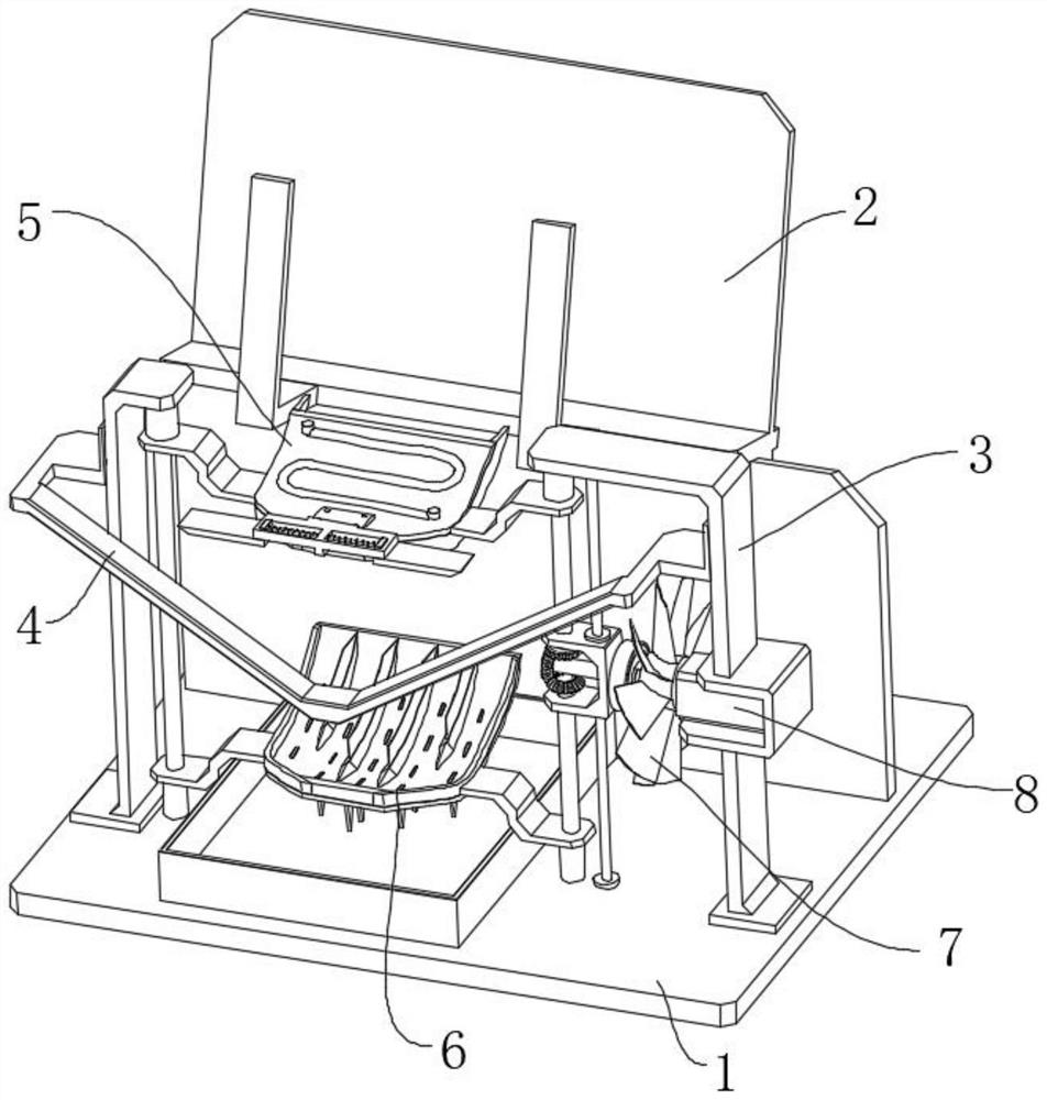
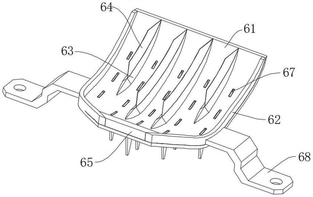
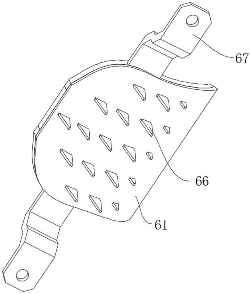
[0040] like Figure 1-Figure 13 A strength detection device based on a 5G dual-polarized antenna is shown, including a base plate 1, a mounting frame 2 and a fixing frame body 3 are fixedly installed on the upper surface of the bottom plate 1, the fixing frame body 3 is located in front of the mounting frame 2, and the fixing frame The front end of the body 3 is equipped with a V-shaped frame 4, and the inner side of the fixed frame body 3 is equipped with an upper pressing mechanism 5 and a lower support mechanism 6. 8 approaching or moving away from each other vertically, wherein:

[0041] The driving mechanism 8 includes a motor 81 fixedly mounted on the inside of the fixed frame body 3, a rotating shaf...


PUM


Abstract

The invention relates to the field of detection equipment, in particular to strength detection equipment based on a 5G dual-polarized antenna, which comprises a bottom plate, a mounting frame and a fixing frame body are fixedly mounted on the upper end surface of the bottom plate, the fixing frame body is located in front of the mounting frame, and a V-shaped frame is mounted on the front end surface of the fixing frame body. An upper pressing mechanism and a lower supporting mechanism are installed on the inner side of the fixing frame body, and the upper pressing mechanism and the lower supporting mechanism get close to each other or get away from each other in the vertical direction through a driving mechanism installed on the inner side of the fixing frame body. And meanwhile, the influence of air flow on the process is simulated, so that the wiring can be assisted to form an arrangement mode during installation, the detection accuracy can be improved, the resistance of the antenna after the surface of the antenna is frozen in winter can be effectively detected, and the purpose of testing the stability of the antenna during use in winter is achieved.

Description

technical field [0001] The invention relates to the field of detection equipment, in particular to a strength detection equipment based on a 5G dual-polarized antenna. Background technique [0002] 5G is the abbreviation of the fifth generation mobile communication technology. It is a new generation of broadband mobile communication technology with the characteristics of high speed, low delay and large connection. The new antenna technology combines +45° and -45° two antennas with orthogonal polarization directions and works in the duplex mode of sending and receiving at the same time, so its most prominent advantage is to save the number of antennas for a single directional base station; [0003] The appearance of the 5G antenna is a rectangular parallelepiped. After being installed at the installation position, several wires are drawn from the bottom of the antenna to connect with the RRU module, which is also called a feeder line. When several wires are drawn out, the wir...

Claims


Application Information

Patent Timeline
Patent Type & Authority Applications(China)
IPC IPC(8): G01N17/00
CPCG01N17/00
Inventor 周文奇黄彩琳刘婕赵德军
Learn More