Automatic angle steel moving and cutting and surface treatment equipment for assembling type roof erection

A surface treatment and assembly technology, applied in shearing machine equipment, metal processing equipment, grinding/polishing equipment, etc., can solve the problems affecting the forming effect of steel floor, reducing the quality of roof forming, and unable to achieve batch processing, etc. Realize the effect of positioning cutting length, improving assembly quality and improving processing efficiency

Pending Publication Date: 2022-03-04
江西博筑工程技术有限公司
View PDF1 Cites 2 Cited by
  • Summary
  • Abstract
  • Description
  • Claims
  • Application Information

AI Technical Summary

Problems solved by technology

[0005] 1. Generally, through manual cutting, it is easy to cause uneven cutting length, which will affect the forming effect after splicing with the steel floor
[0006] 2. When there are depressions and unevenness on the surface of the angle steel, it is easy to have problems such as loose fit when splicing with the steel base plate, which will affect the quality of assembly and reduce the forming quality of the roof. security risks
[0007] 3. Most of the existing equipment only cuts one angle steel at a time, which cannot realize batch processing, which is not conducive to improving cutting efficiency

Method used


Image

  • Automatic angle steel moving and cutting and surface treatment equipment for assembling type roof erection
  • Automatic angle steel moving and cutting and surface treatment equipment for assembling type roof erection
  • Automatic angle steel moving and cutting and surface treatment equipment for assembling type roof erection

Examples


Embodiment Construction

[0038] The technical solutions of the present invention will be further described below in conjunction with the accompanying drawings and through specific implementation methods.

[0039]Wherein, the accompanying drawings are only for illustrative purposes, showing only schematic diagrams, rather than physical drawings, and should not be construed as limitations on this patent; in order to better illustrate the embodiments of the present invention, some parts of the accompanying drawings will be omitted, Enlarged or reduced, does not represent actual product size.

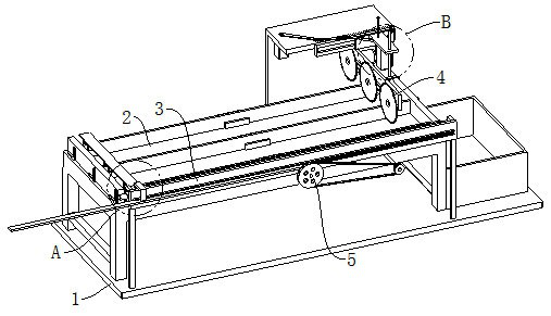
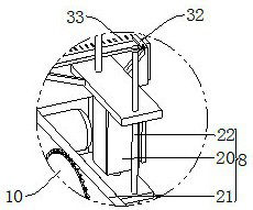
[0040] refer to Figure 1 to Figure 8 The shown one kind of angle steel automatic moving and cutting and surface treatment equipment for erecting a prefabricated roof includes a base 1 and a processing table 2, and also includes a controller, a pushing mechanism 3, a cutting mechanism 4 and a processing mechanism 5, and the pushing mechanism 3 is set on The top of the base 1 is used to push the angle steel. The pu...


PUM


Abstract

The invention relates to the technical field of angle steel machining, in particular to an automatic angle steel moving and cutting and surface treatment device for assembly type roof erection, which comprises a base and a machining table, and further comprises a controller, a pushing mechanism, a cutting mechanism and a treatment mechanism, the pushing mechanism comprises a transferring assembly and three electric clamping jaws, the cutting mechanism is arranged at the top of the base and used for cutting angle steel, the cutting mechanism comprises a lifting assembly, a sliding assembly and three cutters, the processing mechanism comprises a rotating assembly and three grinding wheels, and the three grinding wheels are arranged on the inner wall of the machining table at equal intervals. According to the automatic angle steel moving, cutting and surface treatment equipment for assembly type roof erection, batch machining of angle steel can be achieved, meanwhile, the cutting length of multiple pieces of angle steel can be accurately positioned, waste is avoided, protrusions and the like on the surfaces of the angle steel can be ground, and the flatness of the angle steel can be guaranteed.

Description

technical field [0001] The invention relates to the technical field of angle steel processing, in particular to an angle steel automatic moving and cutting and surface treatment equipment for erecting an assembled roof. Background technique [0002] Angle steel, commonly known as angle iron, is a long strip of steel that is perpendicular to each other and forms an angle. [0003] Assembled roof, this structure is a box-shaped assembled structural unit that is open up and down by connecting angle steel with bolts on the four sides of the steel base plate, and then these assembled structural units are combined and assembled to form a spatial grid roof structure system. The box-type assembly structure unit is composed of a steel base plate with bolt holes on the four sides and a uniform set of studs on the bottom surface, angle steel with bolt holes and prefabricated (cast-in-place) concrete blocks. The steel base plate can be other polygons to assemble into roofs with variou...

Claims


Application Information

Patent Timeline
Patent Type & Authority Applications(China)
IPC IPC(8): B23P23/04B23D19/00B23D33/02B23Q5/28B24B27/00B24B41/00B24B9/04
CPCB23P23/04B23D19/00B23D33/02B23Q5/28B24B27/0076B24B41/005B24B9/04
Inventor 刘凯洪成
Owner 江西博筑工程技术有限公司
Why Eureka
Try Eureka