
Compact multi-user multi-stage multi-target magnetic tracking system

A magnetic tracking, magnetic field technology, applied in the field of magnetic tracking systems, can solve problems such as inapplicability, achieve the effect of less calibration, reduce complexity, and eliminate the need for coil alignment and balance

Pending Publication Date: 2022-03-01
APPLE INC
View PDF0 Cites 0 Cited by
  • Summary
  • Abstract
  • Description
  • Claims
  • Application Information

AI Technical Summary

Problems solved by technology

Conventional three-axis coil transmitter designs used in existing magnetic tracking systems have physical geometries that make the design unsuitable for certain applications requiring housings with thin or flat form factors

Method used


Image

  • Compact multi-user multi-stage multi-target magnetic tracking system
  • Compact multi-user multi-stage multi-target magnetic tracking system
  • Compact multi-user multi-stage multi-target magnetic tracking system

Examples


Embodiment Construction

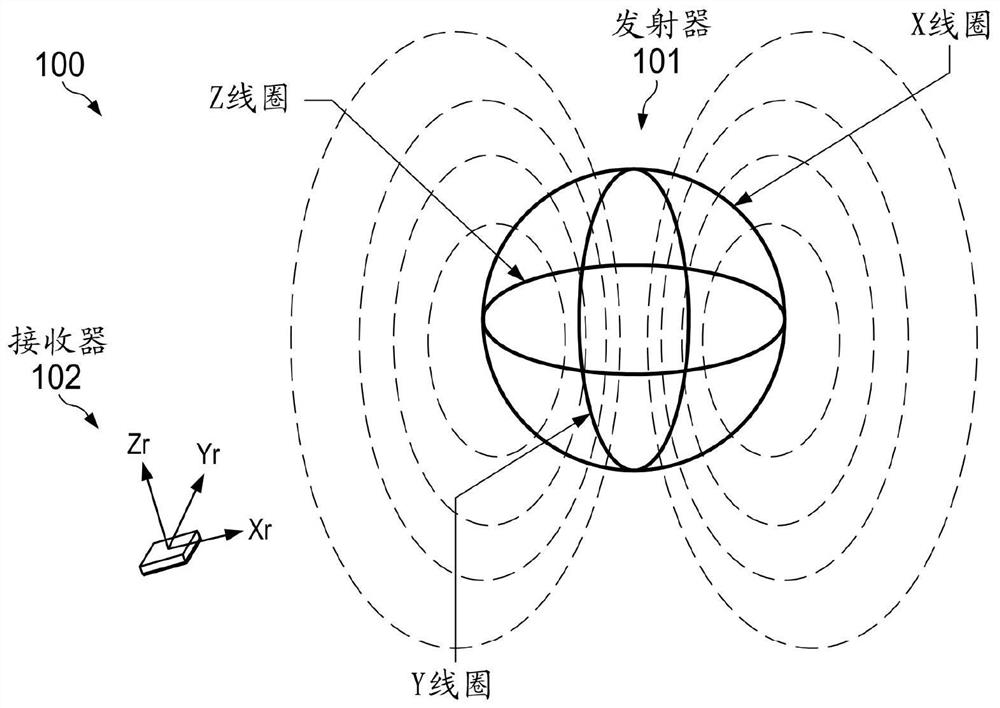
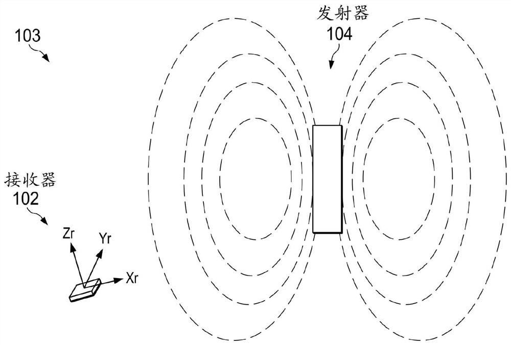
[0022] Figure 1A Shown is a magnetic tracking system 100 comprising a transmitter 101 (Tx), which can be any device with a conventional three-axis coil, and a receiver 102 (Rx), which is used to sense 101 generated magnetic field. In this embodiment and subsequent embodiments described herein, the transmitter 101 is stationary and the receiver 102 (hereinafter also referred to as "target") is tracked by the transmitter 101 . Receiver 102 may include any device having a three-axis magnetometer (eg, coils, Hall sensors, magnetoresistive (MR) sensors). The location (x, y, z) of the receiver 102 is calculated from the sensed magnetic field using techniques known in the art. The specific implementation of the triaxial coils in the transmitter 101 requires significant engineering effort to ensure coil alignment, coil balance and calibration. More importantly, a three-axis coil transmitter design may not be an option in applications requiring a housing with a thin or flat form fac...


PUM


Abstract

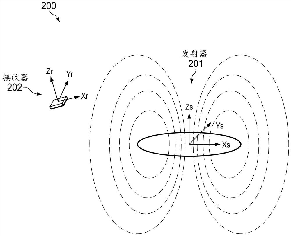
The invention relates to a compact multi-user multi-stage multi-target magnetic tracking system. A compact multi-user magnetic tracking system is disclosed. In one embodiment, compactness is achieved by sensing a magnetic field generated by a single coil and determining the position and attitude of the receiver relative to the transmitter using the single coil and inertial sensor at the transmitter and a magnetometer and inertial sensor at the receiver. The transmitter and the receiver each include a wireless transceiver for exchanging clock synchronization data and transmitting transmitter attitude data to the receiver. In another embodiment, frequency division multiplexing or time division multiplexing is used to differentiate multiple users of the multi-user magnetic tracking system.

Description

technical field [0001] The present disclosure relates to magnetic tracking systems. Background technique [0002] Magnetic tracking systems are used to track the location of moving objects. Existing magnetic tracking systems include base stations or "transmitters" that generate alternating or static electromagnetic fields (hereinafter "magnetic fields") covering three-dimensional (3D) space. The magnetic field is typically emitted by three coils (called "triaxial coils") arranged perpendicular to each other. Alternatively, the three-axis coil is placed in a housing mounted on a mobile platform. A "target" near the transmitter senses changes in the magnetic field as the target moves, and based on that change determines the target's position. Conventional three-axis coil transmitter designs used in existing magnetic tracking systems have physical geometries that make the design unsuitable for certain applications requiring housings with thin or flat form factors. Contents...

Claims


Application Information

Patent Timeline
Patent Type & Authority Applications(China)
IPC IPC(8): G01C21/16G01C21/18
CPCG01C21/165G01C21/18G01S5/00G01R33/0005G01R33/072G01R33/091G01S5/0205G01R33/36G01R33/34G01R33/385
Inventor 段光武郭健J·G·艾里亚斯S·吉德尔
Owner APPLE INC
Learn More