Control method of air source heat pump unit system and air source heat pump unit system
A technology of air source heat pump and control method, which is applied in the control of air source heat pump unit system and the field of air source heat pump unit system, which can solve the problems of poor room comfort and high energy consumption in operation, and improve operation efficiency, reduce energy consumption in operation, The effect of reducing energy waste
- Summary
- Abstract
- Description
- Claims
- Application Information
AI Technical Summary
Problems solved by technology
Method used
Image

Examples
Embodiment 1
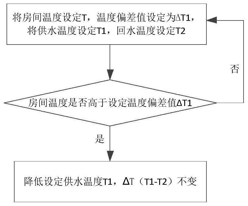
[0059] Such as figure 1 As shown, the present invention provides a control method for an air source heat pump unit system. The air source heat pump unit system is used to adjust the temperature of a room. The control method for the air source heat pump unit system includes the following steps:
[0060] Step 1: Set the temperature of the room as T, and set the temperature deviation as ΔT1;
[0061] Step 2: Set the supply water temperature of the air source heat pump unit system to T1 and the return water temperature to T2 ( figure 1 Combine Step 2 and Step 1 together, there is no sequence relationship between the two);
[0062] Step 3: Determine whether the current temperature deviation value of the air source heat pump unit system room is higher than the set temperature deviation value ΔT1;
[0063] When the current temperature deviation value of the room of the air source heat pump unit system is higher than the set temperature deviation value ΔT1 of the air source heat pum...
Embodiment 2
[0068] The difference between embodiment two and embodiment one is:
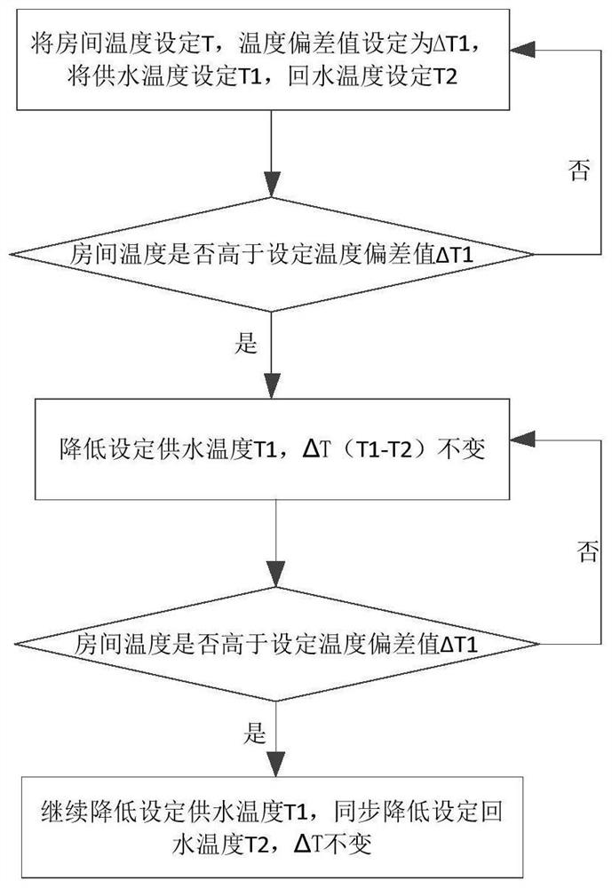
[0069] Specifically, such as figure 2 As shown, in one embodiment, the control method also includes the following steps:
[0070] Step 4: Determine whether the current temperature deviation value of the air source heat pump unit system room is higher than the set temperature deviation value ΔT1 of the air source heat pump unit system;
[0071] When the current temperature deviation value of the air source heat pump unit system room is higher than the air source heat pump unit system set temperature deviation value ΔT1 (if it is), continue to reduce the air source heat pump unit system set water supply temperature T1, and simultaneously reduce the air source heat pump unit The system sets the return water temperature T2, while ensuring that the air source heat pump unit system ΔT remains unchanged;
[0072] When the current temperature deviation value of the room of the air source heat pump unit system is ...
Embodiment 3
[0076] The difference between embodiment three and embodiment two is:
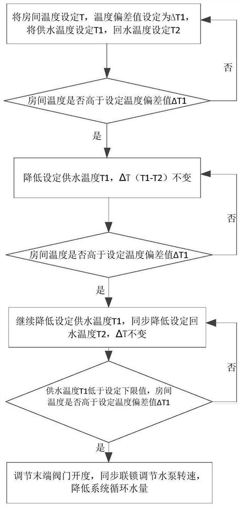
[0077] Specifically, such as image 3 As shown, in one embodiment, the control method also includes the following steps:
[0078] Step 5: Determine whether the current temperature in the room of the air source heat pump unit system is higher than the set temperature deviation value ΔT1 of the air source heat pump unit system when the set water supply temperature T1 of the air source heat pump unit system is lower than the set lower limit temperature;
[0079] When the current temperature of the air source heat pump unit system room is higher than the set temperature deviation value ΔT1 of the air source heat pump unit system (if it is), the opening of the end valve is adjusted, and the speed of the water pump is synchronously interlocked to reduce the circulating water volume of the system;
[0080] When the current room temperature of the air source heat pump unit system is not higher than the set temper...
PUM
 Abstract
Description
Claims
Application Information
 - R&D
- Intellectual Property
- Life Sciences
- Materials
- Tech Scout
- Unparalleled Data Quality
- Higher Quality Content
- 60% Fewer Hallucinations
Browse by: Latest US Patents, China's latest patents, Technical Efficacy Thesaurus, Application Domain, Technology Topic, Popular Technical Reports.
© 2025 PatSnap. All rights reserved.Legal|Privacy policy|Modern Slavery Act Transparency Statement|Sitemap|About US| Contact US: help@patsnap.com