Multi-stage heat recovery fresh air system of central air conditioner
A technology of central air conditioning and fresh air system, applied in air conditioning systems, energy recovery systems for ventilation and heating, ventilation systems, etc., can solve the problems of inability to adjust temperature, large power consumption, slow temperature response, etc., to achieve rapid heating Effect
- Summary
- Abstract
- Description
- Claims
- Application Information
AI Technical Summary
Problems solved by technology
Method used
Image
Examples
Embodiment 1
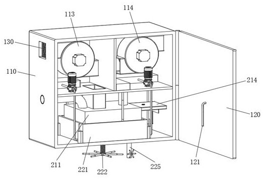
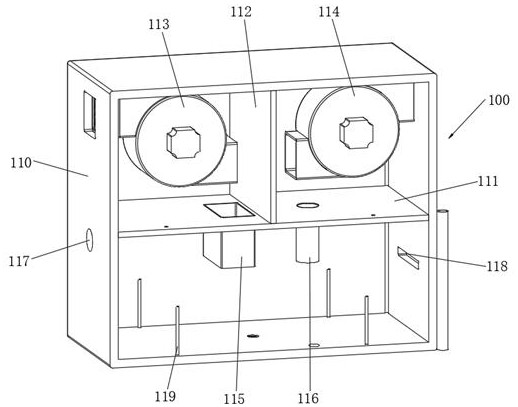
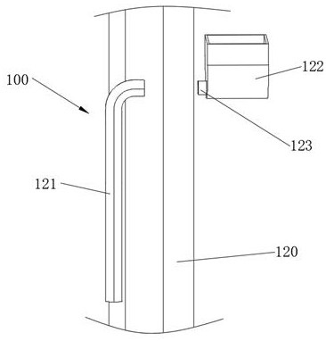
[0048] see Figure 1-Figure 9 As shown, a multi-stage heat recovery fresh air system for a central air conditioner is provided, including an exhaust device 100 and an adjusting device 200 disposed in the exhaust device 100. The exhaust device 100 includes a casing 110 and a cover plate 120, and the casing 110 is provided with a first partition 111, the first partition 111 divides the housing 110 into an installation cavity and a temperature adjustment cavity, a second partition 112 is arranged in the installation cavity, and the second partition 112 divides the installation cavity The cavity is divided into an air inlet cavity and an exhaust air cavity. An air inlet fan 113 is installed in the air inlet cavity, and an exhaust fan 114 is installed in the exhaust air cavity. The bottom of the first partition 111 is connected with a first ventilation pipe 115. And the second ventilation pipe 116, the first ventilation pipe 115 is located at the air inlet cavity, the second ventil...
Embodiment 2
[0059] In order to store hot gas, the following improvements are made on the basis of Example 1:
[0060] see Figure 10 As shown, wherein, one side of the liquid storage box 221 is connected with a transmission rod 240, and one end of the transmission rod 240 is connected with a plug board 241, and the bottom of the air inlet pipe 214 is provided with a slot for plugging in with the plug board 241, considering The liquid storage box 221 cools down the liquid storage box 221 when it rises, but when people feel cold, the indoor temperature is very cold. Therefore, the liquid storage box 221 rises and drives the plate 241 to rise through the transmission rod 240, and the plate 241 rises. 241 rises and inserts into the air inlet pipe 214 to block the air inlet pipe 214, so that the air inlet pipe 214 cannot discharge air, the gas is compressed in the heat exchange cavity 213, and the gas stays in the heat exchange cavity 213 to have sufficient time and The box body 211 is in con...
Embodiment 3
[0062] In order to improve the heating efficiency of the water in the casing 211, the following improvements are made on the basis of Embodiment 2:
[0063] see Figure 11 As shown, wherein, the top of the air inlet pipe 214 is provided with a perforation 242, and a cap 243 is slidably connected to the perforation 242. The side wall of the cap 243 is provided with a plurality of through holes 244. When the air inlet pipe 214 is blocked, the gas is At this time, a large pressure is generated in the air inlet pipe 214 to lift the cap 243, and part of the heat-exchanged gas is discharged into the temperature-regulating cavity through the through-hole 244, so that the temperature of the temperature-regulating cavity is raised, thereby speeding up the heating process. The heating efficiency of the water in the liquid storage box 221 further reduces the waiting time for people to use water.
PUM
 Abstract
Description
Claims
Application Information
 - R&D Engineer
- R&D Manager
- IP Professional
- Industry Leading Data Capabilities
- Powerful AI technology
- Patent DNA Extraction
Browse by: Latest US Patents, China's latest patents, Technical Efficacy Thesaurus, Application Domain, Technology Topic, Popular Technical Reports.
© 2024 PatSnap. All rights reserved.Legal|Privacy policy|Modern Slavery Act Transparency Statement|Sitemap|About US| Contact US: help@patsnap.com


