
Heat dissipation structure of phased-array antenna, phased-array antenna and satellite platform

A phased array antenna and heat dissipation structure technology, which is applied in antenna arrays, antennas, artificial satellites, etc., can solve problems such as high heat flux density, phased array antennas cannot dissipate heat, and poor heat dissipation, so as to optimize heat dissipation paths and shorten heat dissipation Path, the effect of improving the quality of heat dissipation

Pending Publication Date: 2022-02-25
北京九天微星科技发展有限公司
View PDF0 Cites 1 Cited by
  • Summary
  • Abstract
  • Description
  • Claims
  • Application Information

AI Technical Summary

Problems solved by technology

Due to the particularity and complexity of the spaceborne environment, the phased array antenna used on the satellite platform cannot use air cooling and water cooling to dissipate heat, but can only dissipate heat through radiation and heat conduction, and the heat dissipation methods of radiation and heat conduction cannot Provides a constant temperature cooling surface for phased array antennas
However, the existing phased array antennas used in spaceborne environments have high heat flux density and poor heat dissipation capabilities.

Method used


Image

  • Heat dissipation structure of phased-array antenna, phased-array antenna and satellite platform
  • Heat dissipation structure of phased-array antenna, phased-array antenna and satellite platform
  • Heat dissipation structure of phased-array antenna, phased-array antenna and satellite platform

Examples


Embodiment Construction

[0044] In order to enable those skilled in the art to better understand the technical solution of the present invention, the technical solution of the present invention will be further described below in conjunction with the accompanying drawings and through specific implementation methods.

[0045] In the description of the present invention, it should be noted that the terms "upper", "lower", "left", "right", "vertical", "horizontal", "inner", "outer" etc. The positional relationship is based on the orientation or positional relationship shown in the drawings, or the orientation or positional relationship that is usually placed when the product is used. Certain orientations, constructed and operative in certain orientations, therefore are not to be construed as limitations on the invention. In addition, the terms "first" and "second" are only used for descriptive purposes, or for distinguishing different structures or components, and should not be understood as indicating or...


PUM


Abstract

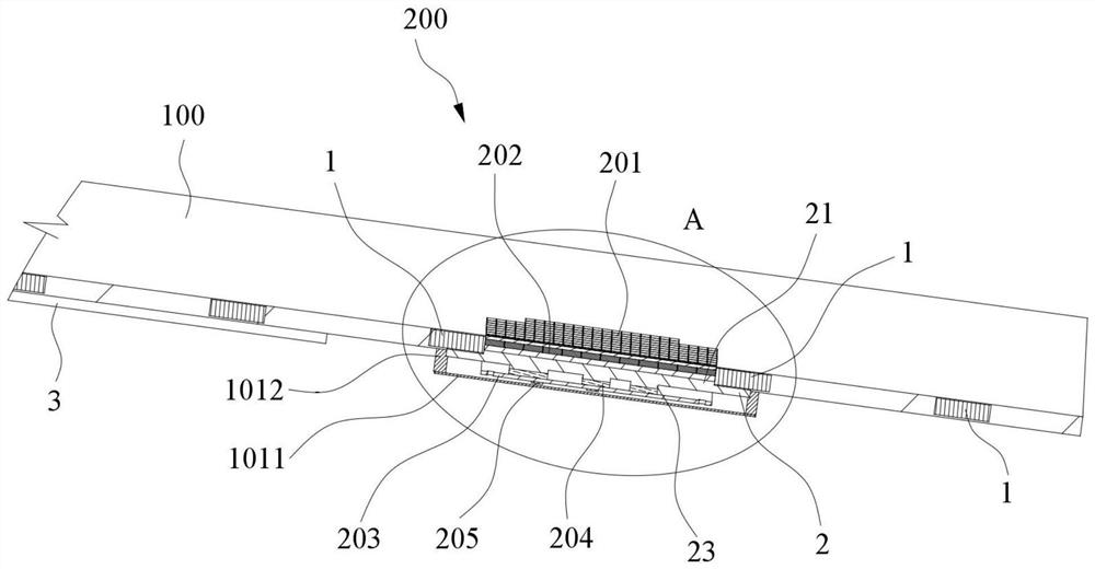
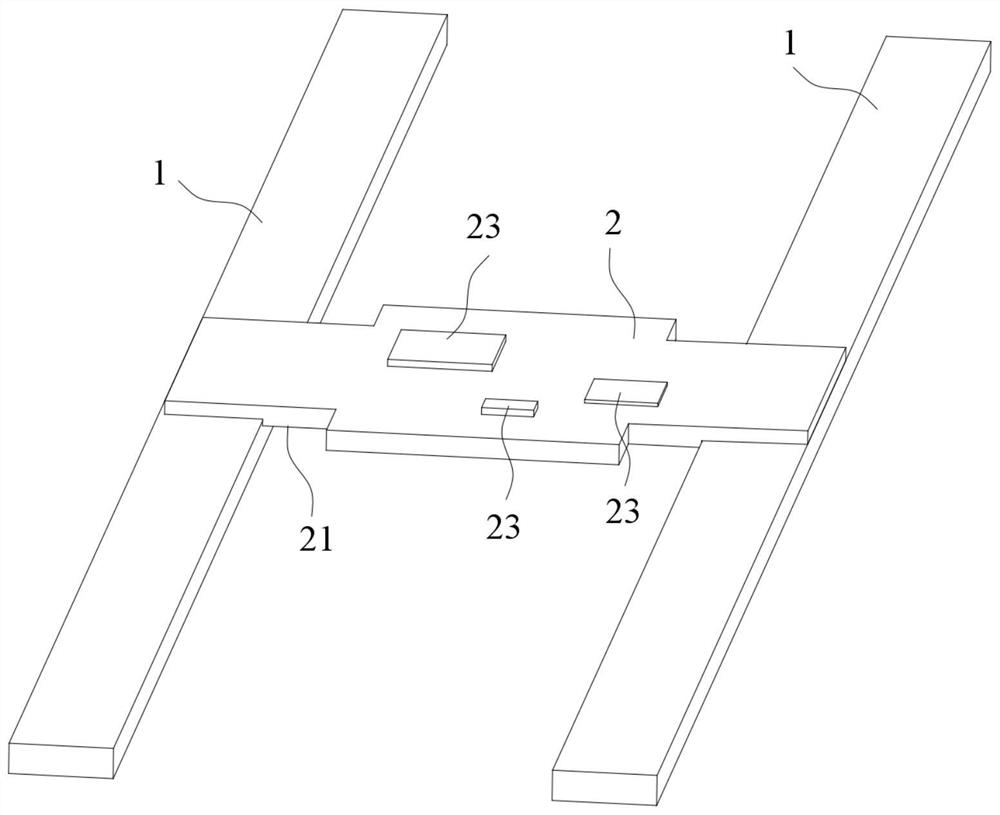
The invention belongs to the technical field of aerospace thermal control and relates to a heat dissipation structure of a phased-array antenna, a phased-array antenna and a satellite platform. The heat dissipation structure of the phased-array antenna is used for conducting heat dissipation on the phased-array antenna of a satellite platform, wherein the satellite platform comprises a satellite cabin plate. The heat dissipation structure of the phased-array antenna comprises a first heat pipe, a flat heat pipe and a second heat pipe; the first heat pipe is buried in the satellite cabin plate; the flat heat pipe is arranged on the inner surface of the satellite cabin plate and used for supporting an antenna assembly of the phased-array antenna; a first protrusion is arranged on the flat heat pipe; the first protrusion is located in the satellite cabin plate, and the outer side face of the first protrusion and a part of the flat heat pipe located on the outer side of the first protrusion are attached to the first heat pipe; and the second heat pipe is arranged on the inner surface of the satellite cabin plate. The heat dissipation structure of the phased-array antenna is small in occupied space; the heat dissipation problem of the antenna assembly is solved; the heat dissipation path is shortened; the heat dissipation efficiency is improved; and normal work of the phased-array antenna on the satellite platform is guaranteed.

Description

technical field [0001] The invention relates to the technical field of aerospace thermal control, in particular to a heat dissipation structure of a phased array antenna, a phased array antenna and a satellite platform. Background technique [0002] At present, the application fields of phased array antennas used for communication functions mainly include space-borne phased array antennas and road-based phased array antennas. Due to the particularity and complexity of the spaceborne environment, the phased array antenna used on the satellite platform cannot use air cooling and water cooling to dissipate heat, but can only dissipate heat through radiation and heat conduction, and the heat dissipation methods of radiation and heat conduction cannot Provides a constant temperature cooling surface for phased array antennas. However, the existing phased array antennas used in spaceborne environments have high heat flux density and poor heat dissipation capability. Contents of ...

Claims


Application Information

Patent Timeline
Patent Type & Authority Applications(China)
IPC IPC(8): H01Q1/02H01Q1/12H01Q1/28H01Q1/38H01Q21/00B64G1/10
CPCH01Q1/02H01Q1/12H01Q1/288H01Q1/38H01Q21/00B64G1/10
Inventor 刘立帅刘彤刘芮
Owner 北京九天微星科技发展有限公司
Learn More