Pixel driving structure and method of OLED display device

A technology for driving structures and display devices, applied in static indicators, instruments, etc., can solve the problems of increasing chip power consumption and cost, increasing power consumption and area, and decreasing product economy, and achieves control of product cost, large size, etc. The effect of drive capability, high display resolution and picture refresh rate

Inactive Publication Date: 2022-02-25
浙江宏禧科技有限公司
View PDF9 Cites 0 Cited by
  • Summary
  • Abstract
  • Description
  • Claims
  • Application Information

AI Technical Summary

Problems solved by technology

However, increasing the driving capability of the op amp will inevitably increase the power consumption and area of ​​each op amp. There are often tens of thousands of columns in the display driver chip depending on the resolution, and the power of the op amp in each column is increased. The power consumption and area will greatly increase the power consumption and cost of the chip, resulting in a decline in product economy

Method used


Image

  • Pixel driving structure and method of OLED display device
  • Pixel driving structure and method of OLED display device
  • Pixel driving structure and method of OLED display device

Examples


Embodiment 1

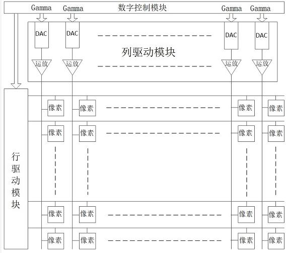
[0035] The pixel drive structure of this embodiment, such as image 3 As shown, it mainly includes a digital control module, a column driver module, a row driver module and a pixel array, where:

[0036] The digital control module mainly includes an interface module, a storage module, a decoder, control logic, and row drive control logic. The interface module is electrically connected to the external device, the column driver module, the storage module, the decoder and the control logic, and is used to transmit the image grayscale digital data (Gamma, which is a digital binary code) in the external device to the decoder and control logic and column driver blocks. The storage module includes a register, and the external device reads and writes the register through the interface module to adjust the value of the register. The number of decoders and control logic is the same as the number of columns of the pixel array. The row driving control logic is electrically connected to...

Embodiment 2

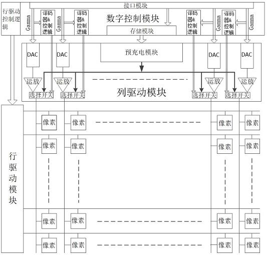
[0055] The pixel driving structure of this embodiment is as follows image 3 As shown, the difference from Embodiment 1 is that in this embodiment, the pre-charging module does not use the voltage division mode, but is designed as Figure 9The structure shown is mainly composed of n pairs of digital-to-analog converters and pre-driver operational amplifiers (n is an integer greater than or equal to 1, which can be set as required). The input end of each digital-to-analog converter is electrically connected to a register in the storage module, and the output end is electrically connected to the input end of the pre-driving operational amplifier. The output terminal of each pre-driver operational amplifier is electrically connected with each selection switch.

[0056] When driving a pixel, see Figure 9 As shown, the values ​​of n registers stored in the storage module in the digital control module are respectively converted into analog voltage values ​​by n DACs in the pre-ch...


PUM


Abstract

The invention discloses a pixel driving structure of an OLED display device. According to the structure, a pre-charging module is additionally arranged in a column driving module, a selection switch is additionally arranged between a conventional operational amplifier and a pixel unit of each column driver, and a preset voltage selection module and control logic are additionally arranged in a digital control module to control the selection switches. The invention also discloses a pixel driving method based on the above structure. According to the method, pre-judgment is performed on gray voltage needed by pixels before conventional driving, the pre-charging module with higher driving capabilities is used to achieve quick pre-driving of pixel data voltage to preset voltage which is close to the gray voltage, and then the pixel data voltage is accurately driven to the gray voltage through the conventional driving. According to the invention, the pre-charging module with the high driving capabilities is added in the column driving module, so that the defect of driving capabilities of a conventional operational amplifier is overcome, and pixel driving capabilities are improved and image quality is ensured under the condition that the area of a chip and power consumption are not greatly increased.

Description

technical field [0001] The invention relates to the field of display technology, in particular to a pixel driving structure and a driving method of an organic light emitting diode (OLED) display device. Background technique [0002] Organic light-emitting diode (OLED) display devices are favored by consumers due to their many advantages such as active light emission, good flexibility, high brightness, and high efficiency. In recent years, OLED display manufacturers have continuously improved the resolution and frame refresh rate of OLED screens in order to provide clearer display effects, which has brought new challenges to the design of driving circuits for OLED pixels. [0003] The traditional pixel driving structure of OLED display devices such as figure 1 As shown, it mainly includes a digital control module, a row driver module, a column driver module (also called a source driver or a data driver) and a pixel array. Among them, the column driving module includes a com...

Claims


Application Information

Patent Timeline
IPC IPC(8): G09G3/3208G09G3/3258
CPCG09G3/3208G09G3/3258G09G2320/0271
Inventor 谢俊杰周昊翔
Owner 浙江宏禧科技有限公司
Why Eureka
Try Eureka