
Second-stage amplifying circuit of two-stage power amplifying circuit

A technology of power amplifier circuit and amplifier circuit, which is applied in the direction of power amplifier, etc., can solve problems such as large voltage and current fluctuations, complex circuits, and large circuit influences, and achieves small current and voltage fluctuations, simple circuit structure, and circuit saving structure effect

Inactive Publication Date: 2015-12-09
ZHENGZHOU JINYUAN ELECTROMECHANICAL EQUIP ENG CO LTD
View PDF0 Cites 0 Cited by
  • Summary
  • Abstract
  • Description
  • Claims
  • Application Information

AI Technical Summary

Problems solved by technology

In the prior art, power amplification generally adopts multi-stage amplification technology. When it is necessary to amplify the power by more than 50 times, generally at least three stages of amplification circuits are required. The higher the base of the amplification circuit, the compatibility, loss, The driving capabilities will affect each other, resulting in increased power consumption of the circuit itself, complex circuits, large fluctuations in voltage and current, and a greater impact on subsequent circuits
In a multi-stage amplifier circuit, the last stage plays a decisive role in the final drive capability. The existing drive capability of the last stage is generally insufficient, so three-stage drive is generally required. How to better design the second stage amplifier circuit, Meeting the requirements of three-level drive with two-level drive has become a difficult problem for technicians

Method used


Image

  • Second-stage amplifying circuit of two-stage power amplifying circuit

Examples


Embodiment Construction

[0007] Below in conjunction with accompanying drawing, the present invention is described in detail.

[0008] In order to make the object, technical solution and advantages of the present invention clearer, the present invention will be further described in detail below in conjunction with the accompanying drawings and embodiments. It should be understood that the specific embodiments described here are only used to explain the present invention, not to limit the present invention.

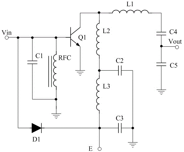
[0009] Such as figure 1 As shown, the principle diagram of the second-stage amplifying circuit of a two-stage power amplifying circuit of the present invention. A second-stage amplifying circuit of a two-stage power amplifying circuit is characterized in that it is composed of a diode D1, an NPN transistor Q1, a high-frequency choke coil RFC, inductors L1-L3, and capacitors C1-C5; the NPN transistor Q1 The base of the inductor is respectively connected to the input terminal Vin, the positive ter...


PUM


Abstract

The invention discloses a second-stage amplifying circuit of a two-stage power amplifying circuit. The circuit is composed of a diode D1, an NPN type triode Q1, a high-frequency choking coil RFC, inductors L1-L3 and capacitors C1-C5; the base of Q1 is connected to an input end Vin, the anode end of D1, one end of C1 and one end of RFC, respectively, and the emitter of Q1 is grounded; the other end of C1 is grounded, while the other end of RFC is grounded; C4 and C5 are connected in series, and then one end is grounded, while the other end is connected to one end of L1; the common end of C4 and C5 is connected to the output end Vout; the other end of L1 is connected to the collector of Q1; the cathode end of D1 is connected to a modulation signal input end E; L2 and L3 are connected in series, and then one end is connected to the collector of Q1, while the other end is connected to E; the common end of L2 and L3 is grounded via C2, and E is grounded via C3. The second-stage amplifying circuit has the beneficial effects of high driving capacity, low output voltage and current fluctuation and wider application range.

Description

technical field [0001] The invention relates to a second-stage amplifying circuit of a two-stage power amplifying circuit. Background technique [0002] A power amplifier circuit is a circuit that amplifies voltage, current and / or power, and is a commonly used circuit in the field of electronic appliances. With the development of electronic and electrical requirements, the requirements for high-power drives are getting higher and higher. In the prior art, power amplification generally adopts multi-stage amplification technology. When it is necessary to amplify the power by more than 50 times, generally at least three stages of amplification circuits are required. The higher the base of the amplification circuit, the compatibility, loss, The driving capabilities will affect each other, resulting in increased power consumption of the circuit itself, complex circuits, large fluctuations in voltage and current, and a greater impact on subsequent circuits. In a multi-stage ampl...

Claims


Application Information

Patent Timeline
IPC IPC(8): H03F3/21
Inventor 韦成辉赵迪刘言言李明
Owner ZHENGZHOU JINYUAN ELECTROMECHANICAL EQUIP ENG CO LTD
Learn More