Building decoration door
A technology for architectural decoration and sliding doors, which is applied to buildings, building components, building structures, etc. It can solve the problems of reduced sealing effect, bringing it into negative pressure wards, and wear of sealing strips, and achieve the effect of improving the sealing effect
- Summary
- Abstract
- Description
- Claims
- Application Information
AI Technical Summary
Problems solved by technology
Method used
Image

Examples
Embodiment 1
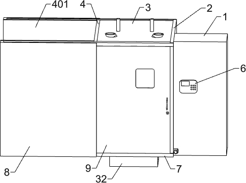
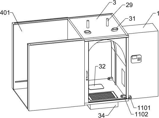
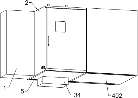
[0033] A kind of architectural decoration door, such as Figure 1-12 As shown, it includes a first vertical plate 2, a U-shaped top plate 3, a second vertical plate 4, a third vertical plate 401, a support plate 402, a bottom plate 5, a door opening mechanism, a disinfection mechanism, ash removing mechanism for the soles of the feet and a locking mechanism. Mechanism, the first vertical plate 2 is installed on the left side of the wall 1, the U-shaped top plate 3 is fixed on the upper left side of the first vertical plate 2, and the second vertical plate 4 is fixed on the U-shaped top plate 3 On the left side, two third vertical plates 401 are arranged, and the two third vertical plates 401 are fixedly connected to the front and rear parts of the left side of the second vertical plate 4 respectively. The lower end is affixed with a support plate 402, the lower ends of the first vertical plate 2 and the second vertical plate 4 are affixed with a bottom plate 5, the first verti...
Embodiment 2
[0036] On the basis of Example 1, such as Figure 1-7 As shown, the door opening mechanism includes a control panel 6, a slideway 7, a protection panel 8, a sliding door 9, an electric wheel 10, a first switch 1101, a second switch 1102, a third switch 1103, a fourth switch 1104 and a sealing assembly, The control board 6 is embedded in the front side of the wall body 1, and two slideways 7 are provided in total. The two slideways 7 are fixedly connected to the front end upper part of the U-shaped top plate 3 and the front end of the bottom plate 5 respectively, and the protective plate 8 is fixedly connected to the On the front side of the left part of the two slideways 7, a second groove 702 is provided at the connection between the two slideways 7 and the base plate 5 and the U-shaped top plate 3 respectively, and three groups of electric wheels 10 are respectively installed on the upper and lower ends of the sliding door 9. The wheels 10 are respectively electrically conne...
Embodiment 3
[0049] On the basis of Example 2, such as Figure 12-13 Shown, also comprise anti-dust mechanism, anti-dust mechanism includes support rod 54, sealing plate 55, connecting shaft 56, square plate 57, support bar 58, slide bar 59, circular plate 60, the 3rd spring 61 and The round sleeve 62 is provided with two support rods 54 in total, and the two support rods 54 are fixedly connected to the left and right sides of the inner surface of the second groove 702, and are provided with two sealing plates 55, and the two sealing plates 55 pass through the connecting shaft 56 hinged, the lower surfaces of the two sealing plates 55 cooperate with the two support rods 54 respectively, the square plate 57 is fixedly connected to the lower part of the inner side of the second groove 702, and the two square plates 57 are arranged on the upper side of the two support rods 54 , the middle part of the square plate 57 is provided with a square through hole, and the front and rear parts of the l...
PUM
 Abstract
Description
Claims
Application Information
 - R&D
- Intellectual Property
- Life Sciences
- Materials
- Tech Scout
- Unparalleled Data Quality
- Higher Quality Content
- 60% Fewer Hallucinations
Browse by: Latest US Patents, China's latest patents, Technical Efficacy Thesaurus, Application Domain, Technology Topic, Popular Technical Reports.
© 2025 PatSnap. All rights reserved.Legal|Privacy policy|Modern Slavery Act Transparency Statement|Sitemap|About US| Contact US: help@patsnap.com