Eureka AIR delivers breakthrough ideas for toughest innovation challenges, trusted by R&D personnel around the world.

Method for carrying out compressed carbon dioxide energy storage on deep aquifer carbon dioxide geological sequestration

A carbon dioxide and geological storage technology, applied in storage devices, heat storage equipment, lighting and heating equipment, etc., can solve the problems of unrecycled heat of compression, low system energy storage efficiency, low system energy storage density, etc. Low, high diffusion coefficient, the effect of improving the energy storage efficiency of the system

Pending Publication Date: 2022-02-25
CHANGSHA UNIVERSITY OF SCIENCE AND TECHNOLOGY
View PDF0 Cites 5 Cited by
  • Summary
  • Abstract
  • Description
  • Claims
  • Application Information

AI Technical Summary

Problems solved by technology

However, the pumped storage power station is limited by the terrain conditions, and its development potential is relatively limited; the compression heat of the traditional compressed air energy storage system is not recycled, and the expansion process relies on the supplementary combustion of fossil fuels such as natural gas. The burned gas will cause environmental pollution, and the energy storage system Low efficiency, low air compressibility, low energy storage density of the system, and relatively large underground space for large-scale energy storage

Method used

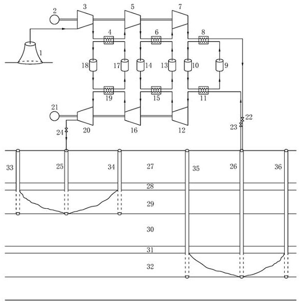
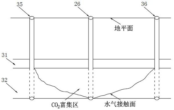
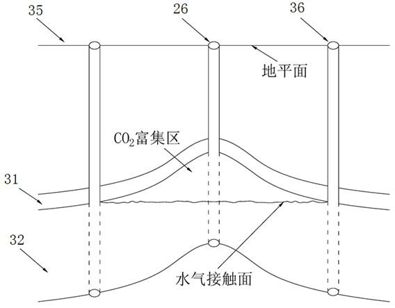

Image

  • Method for carrying out compressed carbon dioxide energy storage on deep aquifer carbon dioxide geological sequestration
  • Method for carrying out compressed carbon dioxide energy storage on deep aquifer carbon dioxide geological sequestration
  • Method for carrying out compressed carbon dioxide energy storage on deep aquifer carbon dioxide geological sequestration

Examples


Embodiment Construction

[0029] The following will clearly and completely describe the technical solutions in the embodiments of the present invention with reference to the accompanying drawings in the embodiments of the present invention. Obviously, the described embodiments are only some, not all, embodiments of the present invention. Based on the embodiments of the present invention, all other embodiments obtained by persons of ordinary skill in the art without making creative efforts belong to the protection scope of the present invention.

[0030]The invention discloses a method for carrying out compressed carbon dioxide energy storage on deep water-bearing (salt water) layer carbon dioxide geological storage, comprising the following steps:

[0031] Step S1, according to the site selection principles of reasonable source-sink matching, suitable reservoir-caprock combination, stable geological structure of the site, no development of earthquakes, volcanoes and active faults, good irritable perform...


PUM


Abstract

The invention discloses a method for carrying out compressed carbon dioxide energy storage on deep aquifer carbon dioxide geological sequestration. The method comprises the steps of engineering site selection, well drilling construction, ground energy storage system arrangement, carbon dioxide transportation, injection and production and system operation period monitoring and feedback. Carbon dioxide generated in industrial activities is purified and collected, is transported to a selected site through a pipeline or a tank car, and is continuously compressed and injected into a water-containing (salt water) layer by utilizing surplus electric power generated by solar energy and wind energy, so that geological storage and electric power storage of the carbon dioxide are realized; part of carbon dioxide is extracted from the salt water layer for power generation in the peak period of power utilization, and the carbon dioxide after power generation is injected into the water-containing (salt water) layer again for storage. The problems of renewable energy power generation volatility, uncontrollability and the like are solved while large-scale storage of carbon dioxide is achieved, and energy conservation and emission reduction and efficient utilization of renewable energy are facilitated.

Description

technical field [0001] The invention belongs to the technical field of carbon dioxide geological storage and electric energy storage, and relates to a method for carrying out compressed carbon dioxide energy storage on deep aquifer carbon dioxide geological storage. Background technique [0002] Atmospheric CO 2 The increase in greenhouse gas content is one of the important reasons for global warming and frequent climate disasters. In order to achieve "carbon peak" and "carbon neutrality" as soon as possible, on the one hand, it is necessary to promote the implementation of CCS (Carbon Capture and Storage, carbon capture and storage) technology; on the other hand, it is necessary to continuously reduce the use of fossil energy and vigorously develop solar and wind energy and other renewable energy. However, the inherent intermittency and instability of renewable energy such as solar energy and wind energy limit their application in grid-connected power generation, resultin...

Claims


Application Information

Patent Timeline
IPC IPC(8): B65G5/00F01K25/10F01K3/00F01K7/22
CPCF01K25/103F01D15/10B65G5/00F28D20/00Y02E60/14Y02C20/40Y02P70/10
Inventor 李毅喻浩刘银江罗贤
Owner CHANGSHA UNIVERSITY OF SCIENCE AND TECHNOLOGY
Why Eureka
Eureka Blog
Learn More