
High-pressure oil rail argon arc welding assembly and manufacturing method thereof

A manufacturing method and argon arc welding technology, applied in manufacturing tools, arc welding equipment, welding equipment, etc., can solve the problems of waste of resources, large equipment occupancy, inability to adjust, etc., to shorten the process route, improve production efficiency, reduce The effect of occupancy

Active Publication Date: 2022-02-25
SHANGHAI WINKELMANN LONGCHUAN (SWL) MOTORCOMPONENTS CO LTD
View PDF9 Cites 0 Cited by
  • Summary
  • Abstract
  • Description
  • Claims
  • Application Information

AI Technical Summary

Problems solved by technology

However, the angle of the injector seat produced by this process cannot be guaranteed, the main reasons are as follows:
[0004]In the process of welding the oil through seat and the injector seat to form an assembly, the angle of the injector seat slot is 37°±1°, which is the process characteristic of this process , cannot adjust
When entering the follow-up process and forming the final high-pressure oil rail argon arc welding assembly from the assembly, under the premise of ensuring that the inner diameter arc surface on the oil passage seat fits closely with the outer diameter arc surface of the distribution pipe, the oil injection The relative deflection will always occur when the slot angle of the holder is 37°±1°, and the angle cannot be guaranteed to be qualified
At the same time, the above process requires separate welding, and it needs to be welded three times, and the equipment occupies a large amount, which directly causes a waste of resources

Method used


Image

  • High-pressure oil rail argon arc welding assembly and manufacturing method thereof
  • High-pressure oil rail argon arc welding assembly and manufacturing method thereof
  • High-pressure oil rail argon arc welding assembly and manufacturing method thereof

Examples


Embodiment Construction

[0037] The present invention will be further described below in combination with specific embodiments. It should be understood that these examples are only used to illustrate the present invention and are not intended to limit the scope of the present invention. In addition, it should be understood that after reading the teachings of the present invention, those skilled in the art can make various changes or modifications to the present invention, and these equivalent forms also fall within the scope defined by the appended claims of the present application.

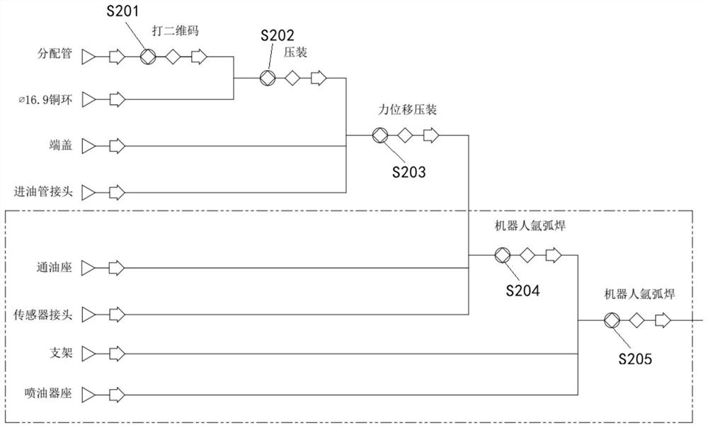
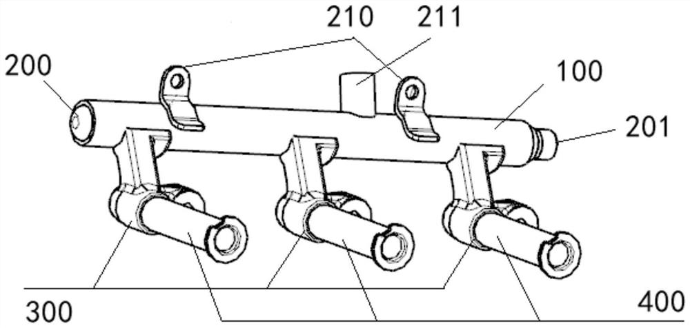
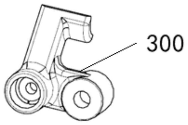
[0038] see Figure 2 to Figure 8 , the invention discloses a high-pressure oil rail argon arc welding assembly manufactured by using a manufacturing method of a high pressure oil rail argon arc welding assembly of the present invention. As shown in the figure, one of the preferred embodiments consists of a distribution pipe 100, an end cover 200, an oil inlet pipe joint 201, a bracket 201, a sensor joint 211, and an oil...


PUM


Abstract

The invention relates to the field of automobile high-pressure oil rails, and in particular, relates to a high-pressure oil rail argon arc welding assembly and a manufacturing method thereof. Components of the high-pressure oil rail argon arc welding assembly are divided into a distribution pipe, a first-stage component directly and independently connected to the distribution pipe, a connecting component used for connecting the distribution pipe with other components and a second-stage component connected with the distribution pipe through the connecting component. The manufacturing method comprises the steps that: firstly, a press-fitting component in the first-stage component is connected to the distribution pipe by adopting a press-fitting process; then a first welding component and the connecting component in the first-stage component are connected to the distribution pipe through first-time argon arc welding; and finally, a second welding component and the second-stage component in the first-stage component are connected to the distribution pipe through second argon arc welding. The invention further comprises the high-pressure oil rail argon arc welding assembly. On the premise that the location degree and the outline of a product are guaranteed, the fixed included angle between an oil sprayer seat clamping groove and the distributing pipe in the radial direction is guaranteed, the process route is shortened, and the production efficiency is improved.

Description

technical field [0001] The invention relates to the field of high-pressure fuel rails for automobiles, in particular to a high-pressure fuel rail argon arc welding assembly and a manufacturing method. Background technique [0002] see figure 1 , the high-pressure oil rail argon arc welding assembly is composed of a distribution pipe 100, an end cover 200, an oil inlet pipe joint 201, a sensor joint 211, an oil passage seat 300, a bracket 210, and an injector seat 400 fixed on the oil passage seat 300 . The product drawings require to ensure the position and contour of the product, and at the same time ensure that the angle between the slot 4001 of the injector seat 400 and the radial direction of the distribution pipe 100 is an angle of 37°±1°. [0003] see Figure 9 , in the production process of the high-pressure oil rail argon arc welding assembly of the prior art, in the distribution pipe 100 that has completed the two-dimensional code printing and the end cap 200 and...

Claims


Application Information

Patent Timeline
IPC IPC(8): B23K9/16B23K9/235F02M55/02
CPCB23K9/16B23K9/235F02M55/02B23K2101/006
Inventor 杨旭程水良张琴琴
Owner SHANGHAI WINKELMANN LONGCHUAN (SWL) MOTORCOMPONENTS CO LTD
Learn More