Lathe tool damping device

A shock-absorbing device and turning tool technology, which is applied in the direction of cutting tools used in lathes, turning equipment, tool holder accessories, etc., can solve problems such as reducing tool life, affecting workpiece machining accuracy, and aggravating tool wear, so as to improve efficiency , low cost, and the effect of ensuring machining accuracy

Pending Publication Date: 2022-02-25
陈素丽
View PDF7 Cites 4 Cited by
  • Summary
  • Abstract
  • Description
  • Claims
  • Application Information

AI Technical Summary

Problems solved by technology

When machining deep holes on a machine tool, generally the blade is installed on the cutter head of the tool holder. When processing deep holes, due to the long cutter holder and the heavy weight of the cutter head, chattering is very easy to occur during processing. Not only affects the machining accuracy of the workpiece, but also aggravates the wear of the tool, greatly reducing the service life of the tool
The Chinese invention application with the notification number CN110142424A discloses a turning tool shock absorber for a numerically controlled lathe, specifically disclosing that a tool bar mounting seat is provided at the right end of the second tool bar, and mounting grooves are provided on the upper and lower sides of the tool bar mounting seat , fix the second knife rod in the installation groove, and then install a shock absorbing device between the installation groove and the knife rod. Large, the vibration of the lathe itself is easily transmitted to the tool bar. Furthermore, the shock absorbing device in this technical solution uses a spring. Since the spring needs to be displaced relative to the shock absorbing effect, it cannot achieve a good shock absorbing effect. , leading to poor shock absorption

Method used


Image

  • Lathe tool damping device
  • Lathe tool damping device
  • Lathe tool damping device

Examples


Embodiment Construction

[0025] Embodiments of the present invention are described below through specific examples, and those skilled in the art can easily understand other advantages and effects of the present invention from the content described in this specification. The present invention can also be implemented or applied through other different specific implementation modes, and various modifications or changes can be made to the details in this specification based on different viewpoints and applications without departing from the spirit of the present invention. It should be noted that the diagrams provided in the following embodiments are only schematically illustrating the basic concept of the present invention, and the following embodiments and the features in the embodiments can be combined with each other in the case of no conflict.

[0026] Wherein, the accompanying drawings are for illustrative purposes only, and represent only schematic diagrams, rather than physical drawings, and should...


PUM


Abstract

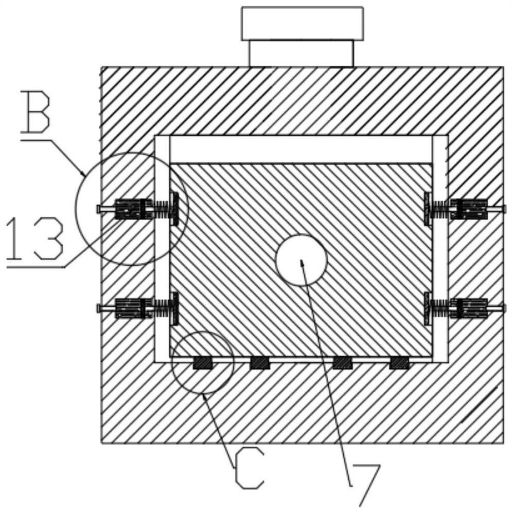
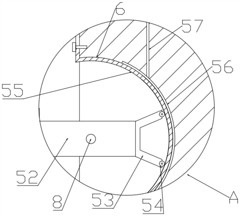
The invention discloses a lathe tool damping device, and belongs to the technical field of mechanical equipment. The lathe tool damping device comprises a tool bar and a tool bar mounting seat; one end of the tool bar mounting seat is provided with a mounting groove for mounting the tool bar, and an opening of the mounting groove is provided with a fixing part for fixing the tool bar; the tail part of the tool bar is fixed in the mounting groove, a tool bar extension section is fixedly arranged at the rear end of the tool bar, a movable gap is formed between the tool bar extension section and the inner wall of the mounting groove, and the tool bar extension section is connected with a swing damping device; and the swing damping device comprises a swing rod, a connecting rod, an n-shaped supporting frame, a friction roller and an arc-shaped damping face. According to the device, the influence of vibration of a lathe on the tool bar can be reduced, vibration of the tool bar can be damped at the same time, the damping effect is better, and thus the influence of vibration on processing of the tool bar is reduced, and the processing precision can be effectively guaranteed.

Description

technical field [0001] The invention belongs to the technical field of mechanical equipment, and in particular relates to a shock absorbing device for a turning tool of a lathe. Background technique [0002] A turning tool is a tool with one cutting part for turning, and is one of the most widely used tools in cutting. When machining deep holes on a machine tool, generally the blade is installed on the cutter head of the tool holder. When processing deep holes, due to the long cutter holder and the heavy weight of the cutter head, chattering is very easy to occur during processing. It not only affects the machining accuracy of the workpiece, but also aggravates the wear of the tool and greatly reduces the service life of the tool. The Chinese invention application with the notification number CN110142424A discloses a turning tool shock absorber for a numerically controlled lathe, specifically disclosing that a tool bar mounting seat is provided at the right end of the secon...

Claims


Application Information

Patent Timeline
Patent Type & Authority Applications(China)
IPC IPC(8): B23B27/00B23B29/02F16F15/02
CPCB23B27/00B23B29/022F16F15/02Y02P70/10
Inventor 陈素丽
Owner 陈素丽
Why Eureka
Try Eureka