Suction combined type solidification spraying device

A spray device, combined technology

Active Publication Date: 2022-02-25
SOUTHWEST PETROLEUM UNIV +1
View PDF20 Cites 0 Cited by
  • Summary
  • Abstract
  • Description
  • Claims
  • Application Information

AI Technical Summary

Problems solved by technology

[0002] Microbe-induced calcium carbonate precipitation (MICP) technology uses the microbial mineralization that is ubiquitous in nature to induce the production of calcium carbonate crystals in the soil by spraying bacterial fluid and cementing fluid (usually a mixed solution of urea and calcium salt) inside the soil. , improve the compactness of the sand and the cementation between the particles, thereby improving the mechanical properties of the soil layer; however, when the existing grouting pipe is grouted, the grouting port at the bottom of the grouting pipe is usually equipped with a spray structure, to facilitate the injection of slurry, because high-concentration bacterial solution can quickly hydrolyze urea to form mineralized crystals, so it is easy to cause calcium carbonate crystals to accumulate and cause blockage of the injection structure, thereby affecting the smooth infiltration of subsequent slurry, especially in the face of large areas When solidifying the work object, the clogging phenomenon of the grouting port is more obvious

Method used


Image

  • Suction combined type solidification spraying device
  • Suction combined type solidification spraying device
  • Suction combined type solidification spraying device

Examples


Embodiment 1

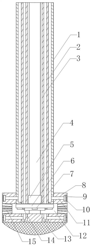
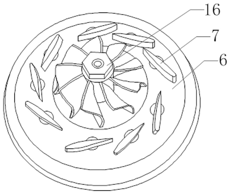
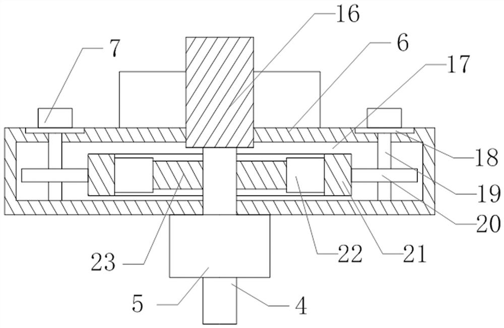
[0032] Such as Figures 1 to 5 As shown, the present embodiment includes a cylindrical spray nozzle 8, the middle part of the spray nozzle 8 is provided with a rotary spray chamber 12, and the upper end surface of the spray nozzle 8 is provided with an outer casing 1 communicating with the rotary spray chamber 12. There is a rotating shaft 4 inside, and a disc 6 is arranged in the rotary spray chamber 12. The lower end of the rotating shaft 4 moves through the middle of the disc 6 and then extends downward, and a turbine 16 is arranged on the extension of the rotating shaft 4. Along the spray head 8 A plurality of jet orifice groups 15 communicating with the inside of the swirl spray chamber 12 are arranged at intervals on its outer peripheral wall in the circumferential direction, and a plurality of deflectors 7 are rotated on the lower surface of the disc 6, and a plurality of deflectors 7 Distributed around the turbine 16 in an annular array, an adjustment cavity 17 is open...

Embodiment 2

[0037] Such as Figures 1 to 5 As shown, this embodiment also includes an inner sleeve 3 coaxial with the outer sleeve 1, and a cylinder 2 is also provided between the outer sleeve 1 and the inner sleeve 3, and between the outer sleeve 1 and the cylinder 2 , An annular space is formed between the cylinder body 2 and the inner casing 3, and an annular baffle is arranged at the lower end of the outer casing 1, and the annular baffle seals the bottom of the annular space between the outer casing 1 and the cylinder 2, so The lower end of the cylinder 2 is provided with an annular baffle, which seals the bottom of the annular space between the inner sleeve 3 and the cylinder 2, and a plurality of shunt pipes 24 are arranged on the lower surface of the annular baffle to divert the flow. The pipe 24 communicates with the annular space between the inner casing 3 and the cylinder body 2, and a plurality of distribution pipes 24 are placed in the wall of the nozzle 8, and a plurality of...

Embodiment 3

[0042] Such as Figures 1 to 5As shown, this embodiment is on the basis of Embodiment 1. The nozzle includes a guide tube 11, a buffer chamber 9, and a plurality of air holes 10 communicating with the buffer chamber 9. The buffer chamber 9 is set in the wall of the nozzle 8, and a plurality of The air holes 10 are provided on the outer peripheral wall of the nozzle 8, one end of the guide tube 11 communicates with the buffer chamber 9, the other end of the guide tube 11 communicates with the shunt tube 24, the annular space between the outer sleeve 1 and the cylinder body 2 connected. The two groups of nozzles realize the pumping function of the fluid respectively, and the two groups of spray groups are respectively located above and below the jet hole group 15; Flow into the buffer chamber 9, and then evenly disperse to the wall of the pile hole 28 through the multi-channel air holes 10, and when the suction is performed, the mixed liquid of the cleaning liquid and the mud i...


PUM


Abstract

The invention discloses a suction combined type solidification spraying device, which relates to the field of fluid spraying and specifically comprises a spraying head, an outer sleeve is arranged on the upper end surface of the spraying head, a rotating shaft is arranged in the outer sleeve, a turbine is arranged on the extension section of the rotating shaft, a plurality of jet hole groups are formed in the outer circumferential wall of the spraying head, and a plurality of flow guide plates are rotationally arranged on the lower surface of a disc. An adjusting cavity is formed in the disc, a linkage assembly is arranged in the adjusting cavity, and fan blades of the turbine directly face the jet flow hole set. The slurry is horizontally pushed and permeated into a soil body in a transverse permeation grouting mode and a rotary spraying mode, in the low-pressure spraying process, the slurry overflows out of the spraying head at a proper flow speed by means of the adjusting functions of a turbine in the spraying head and a plurality of flow guide plates, and on the premise that it is ensured that bacterial cells are not separated from the slurry, the horizontal transmission distance of slurry is increased.

Description

technical field [0001] The invention relates to the field of fluid injection, and specifically provides a suction combined curing injection device. Background technique [0002] Microbe-induced calcium carbonate precipitation (MICP) technology uses the microbial mineralization that is ubiquitous in nature to induce the production of calcium carbonate crystals in the soil by spraying bacterial fluid and cementing fluid (usually a mixed solution of urea and calcium salt) inside the soil. , improve the compactness of the sand and the cementation between the particles, thereby improving the mechanical properties of the soil layer; however, when the existing grouting pipe is grouted, the grouting port at the bottom of the grouting pipe is usually equipped with a spray structure, to facilitate the injection of slurry, because high-concentration bacterial solution can quickly hydrolyze urea to form mineralized crystals, so it is easy to cause calcium carbonate crystals to accumulat...

Claims


Application Information

Patent Timeline
Patent Type & Authority Applications(China)
IPC IPC(8): B05B1/14B05B1/26B05B1/30B05B1/32B05B1/34B05B15/50
CPCB05B1/14B05B1/30B05B1/267B05B15/50B05B1/32B05B1/341B05B1/34
Inventor 郭亮何肖玉何妮张敏熊柱红张锦涛曾未名彭颐祈郭馨艺姜宇宏王保权赵金龙文海旭李媛媛王泓智王雅坤王梓同廖明伟郭豪吴海龙鄢睿刘丰威路益王云翔邢雷戴启辰罗鹏刘芯邑
Owner SOUTHWEST PETROLEUM UNIV
Why Eureka
Try Eureka