Eureka AIR delivers breakthrough ideas for toughest innovation challenges, trusted by R&D personnel around the world.

Double-floating sealing test device for simulating muddy water working condition

A sealing test, double floating technology, applied in the direction of measuring the increase and decrease rate of the fluid, using the liquid/vacuum degree to measure the liquid tightness, etc., can solve the shaft deformation, the difficulty of installing the double floating seal with large shaft diameter, and the axial force Unbalance and other problems can be solved to reduce the test error, avoid the shafting movement and the increase of the main shaft deflection, and achieve the effect of high reliability

Pending Publication Date: 2022-02-18
HEFEI GENERAL MACHINERY RES INST
View PDF0 Cites 0 Cited by
  • Summary
  • Abstract
  • Description
  • Claims
  • Application Information

AI Technical Summary

Problems solved by technology

[0003] The purpose of the present invention is to overcome the above-mentioned deficiencies in the prior art, and provide a reasonable and practical dual-floating seal test device for simulating muddy water conditions. The seal is in a good lubricating environment; at the same time, it also solves the problems of large shaft diameter double floating seals that are difficult to install, easy to deform the shaft, and unbalanced axial force

Method used


Image

  • Double-floating sealing test device for simulating muddy water working condition
  • Double-floating sealing test device for simulating muddy water working condition
  • Double-floating sealing test device for simulating muddy water working condition

Examples


Embodiment Construction

[0032] For ease of understanding, the specific structure and working method of the present invention are further described as follows:

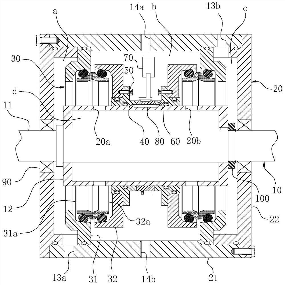
[0033] The concrete implementation structure of the present invention refers to Figure 1-3 As shown, the main structure includes a housing 20 and two sets of symmetrically distributed double floating seals 30 located in the inner cavity of the housing 20, wherein:

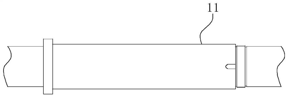
[0034] The main shaft 10 is composed of a shaft body 11 and a shaft sleeve 12 keyed on the shaft body 11. The shaft sleeve 12 is sleeved and pressed against the figure 2 After the shaft shoulder of the shaft body 11 shown, rely on the tightening action of the axial nut 100 to axially compress the shaft sleeve 12 on the shaft shoulder; if necessary, additional Arrange snap rings or snap rings, etc., to play the anti-loosening function; of course, other fixed fit methods can also be used in actual operation. The housing 20 includes an outer cylinder 21 and a left-right symmetric...


PUM


Abstract

The invention relates to the technical field of sealing tests, in particular to a double-floating sealing test device for simulating a muddy water working condition. The device comprises a main shaft, a shell and two groups of double floating seals, wherein the double floating seals are symmetrically arranged at two ends of the main shaft in a sleeving manner; static ring seats of the two groups of double floating seals extend towards the shell wall of the shell and are fixed on the shell wall, so that an inner cavity is divided into a left lubricating cavity, a middle working cavity and a right lubricating cavity which are isolated from one another; and moving ring seats of the two groups of double floating seals are fixed on the main shaft, and are in dynamic and static sealing fit through the moving rings at the moving ring seats and the static rings at the static ring seats. According to the invention, the operation condition of the double-floating seal in a muddy water environment can be simulated, and the seal is in a good lubrication environment; meanwhile, the problems that a large-shaft-diameter double-floating seal is difficult to install, a shaft is prone to deformation, axial force is unbalanced and the like are solved.

Description

technical field [0001] The invention relates to the technical field of sealing tests, in particular to a double-floating sealing test device for simulating muddy water conditions. Background technique [0002] The double floating end face seal is generally composed of a pair of metal floating rings with high end face hardness and the corresponding rubber O-ring and floating seal seat, and the end face seal is formed by compressing the O-ring axial pressure. Because of its special structure, it can be applied to harsh working conditions such as muddy water, and has the advantages of simple structure, wear resistance, vibration and impact resistance, good sealing performance and long service life. The seals of the two ends of the road wheel, the drum of the shearer, the reducer and other construction machinery are used to prevent muddy water and other media from entering the sealing cavity to damage the bearing, so as to ensure that the equipment is in a good operating environ...

Claims


Application Information

Patent Timeline
Patent Type & Authority Applications(China)
IPC IPC(8): G01M3/26
CPCG01M3/26
Inventor 王永乐吴兆山李凤成丁思云郑国运谢星刘杰李香张晓东沈宗沼姚黎明李鲲
Owner HEFEI GENERAL MACHINERY RES INST
Why Eureka
Eureka Blog
Learn More