
Electrolytic hydrogen production system and temperature control method and device thereof

A temperature control method and technology of a temperature control device, which are applied to electrolysis components, electrolysis processes, cells, etc., can solve the problems of changes in the input power of electrolyzers, affecting the effect of temperature regulation, and delaying the action of regulating valves, so as to improve the safety performance of the system. and operation reliability, improve temperature regulation effect, and improve the effect of response speed

Pending Publication Date: 2022-02-18
阳光氢能科技有限公司
View PDF3 Cites 1 Cited by
  • Summary
  • Abstract
  • Description
  • Claims
  • Application Information

AI Technical Summary

Problems solved by technology

[0004] However, the existing temperature control technology must first detect the temperature signal, and then adjust the valve opening through the control algorithm and the execution unit, which has the following problems: the time from the change of system power to the change of system temperature and being recognized by the temperature sensor is relatively long, And there is a certain delay in the action of the regulating valve, which leads to a long cycle of the entire temperature regulation and a serious lag in response. When the energy of the electrolytic cell is provided by new energy, the fluctuation of the new energy power will cause rapid changes in the input power of the electrolytic cell, and the temperature The adjustment speed cannot meet the requirements of rapid changes in input power, which will affect the temperature adjustment effect and easily cause the temperature in the electrolytic cell to rise, resulting in the shutdown of the equipment due to overtemperature, posing a safety hazard

Method used


Image

  • Electrolytic hydrogen production system and temperature control method and device thereof
  • Electrolytic hydrogen production system and temperature control method and device thereof
  • Electrolytic hydrogen production system and temperature control method and device thereof

Examples


Embodiment 1

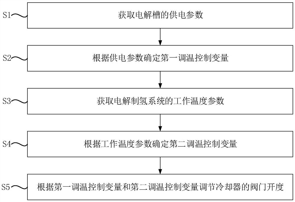
[0049] figure 1 It is a flow chart of a temperature control method for an electrolytic hydrogen production system provided in Embodiment 1 of the present invention. This embodiment is applicable to an electrolytic hydrogen production system that uses a new energy power supply as a hydrogen production power supply. The hydrogen production power supply is used for electrolysis The electrolyzer of the hydrogen production system supplies power, and the electric energy provided by the hydrogen production power supply fluctuates, and the method can be performed by a temperature control device configured with corresponding functional modules and / or software programs.

[0050] In this embodiment, the electrolytic hydrogen production system includes an electrolytic cell, a hydrogen-oxygen-liquid separator, a cooler, a circulating pump, and a control unit. A valve is set at the inlet end of the cooling liquid of the cooler, and the control unit adjusts the cooling liquid by adjusting the...

Embodiment 2

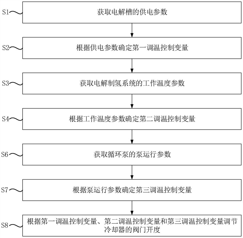
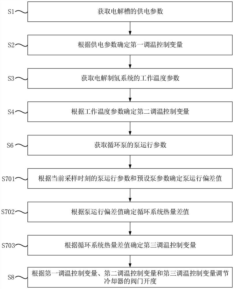
[0072] figure 2 It is a flow chart of a temperature control method for an electrolytic hydrogen production system provided in Embodiment 2 of the present invention. exist figure 1 On the basis of the illustrated embodiment, this embodiment adds a technical solution of detecting the pump operation parameters of the circulating pump and calculating the feedforward compensation control variable.

[0073] Such as figure 2 As shown, the temperature control method specifically includes the following steps:

[0074] Step S1: Obtain the power supply parameters of the electrolyzer.

[0075] Step S2: Determine the first temperature adjustment control variable according to the power supply parameters.

[0076] Step S3: Obtain the operating temperature parameters of the electrolytic hydrogen production system.

[0077] Step S4: Determine the second temperature regulation variable according to the working temperature parameter.

[0078] Step S6: Obtain the pump operating parameters...

Embodiment 3

[0101] Based on any of the above-mentioned embodiments, Embodiment 3 of the present invention provides a temperature control device for an electrolytic hydrogen production system. The temperature control device provided in the embodiment of the present invention can execute the temperature control method provided in any embodiment of the present invention. It has the corresponding functional modules and beneficial effects of the execution method.

[0102] Figure 4 It is a schematic structural diagram of a temperature control device for an electrolytic hydrogen production system provided in Embodiment 3 of the present invention.

[0103] Such as Figure 4 As shown, the temperature control device 00 includes: a power supply parameter acquisition unit 10 , a temperature detection unit 20 and a control unit 30 . Among them, the power supply parameter acquisition unit 10 is used to acquire the power supply parameters of the electrolyzer; the temperature detection unit 20 is used...


PUM


Abstract

The invention discloses an electrolytic hydrogen production system and a temperature control method and device thereof. The method comprises the steps: obtaining a power supply parameter of an electrolytic bath; determining a first temperature regulation control variable according to the power supply parameter; obtaining a working temperature parameter of the electrolytic hydrogen production system; determining a second temperature regulation control variable according to the working temperature parameter; and adjusting the valve opening degree of the cooler according to the first temperature adjustment control variable and the second temperature adjustment control variable. The control variables required for temperature regulation are calculated through the power supply parameters of the electrolytic bath and the working temperature parameters of the system, the working temperature of the hydrogen production system is actively regulated, the temperature regulation response speed is increased, the temperature regulation effect is improved, and the safety performance and the operation reliability of the system are improved.

Description

technical field [0001] The invention relates to the technical field of electrolytic hydrogen production, in particular to an electrolytic hydrogen production system and a temperature control method and device thereof. Background technique [0002] The electrolytic hydrogen production system is a system that uses electrolyzed water as the raw material to produce high-purity hydrogen from water electrolyzers, hydrogen-oxygen liquid separators, coolers, and circulating pumps. [0003] In the electrolytic water hydrogen production system, it is necessary to control the working temperature of the electrolytic hydrogen production equipment. The existing temperature control adopts a passive control method, and a closed-loop control system is composed of a temperature sensor, a control system and a cooler valve. The hydrogen and oxygen generated by electrolysis in the electrolyzer enter the hydrogen-oxygen liquid separator together with the electrolyzed water, and the outlet temper...

Claims


Application Information

Patent Timeline
IPC IPC(8): C25B1/04C25B15/027C25B9/00C25B9/67
CPCC25B1/04C25B15/027C25B9/00C25B9/67Y02E60/36
Inventor 陈志权李江松柏杨张杰
Owner 阳光氢能科技有限公司
Learn More