


Quick Research
Generate reliable direction feasibility study reports for your R&D in just a few steps.

Technical Q&A
Discover and master advanced knowledge NOW. Basics, ideas, possibilities, all at once.

Find Solutions
As an expert in R&D theories, this can generate solutions to your technical problems instantly.

Evaluate Feasibility
Analyze your overall solution with one click, know your potential R&D risks in advance.

Monitor Landscape
Get weekly tech updates, stay abreast of the latest tech innovations and key insights.
Rotational molding integrally-formed oil tank with oil blocking structure
A fuel tank, integrated technology, applied in the field of rotomolding integrated fuel tank, can solve the problems of energy consumption, insufficient engine power, liquid level change, etc., and achieve the effect of reducing damage, eliminating or reducing inertial impact force
- Summary
- Abstract
- Description
- Claims
- Application Information
AI Technical Summary
Problems solved by technology
Method used
Image

Examples
Embodiment 1
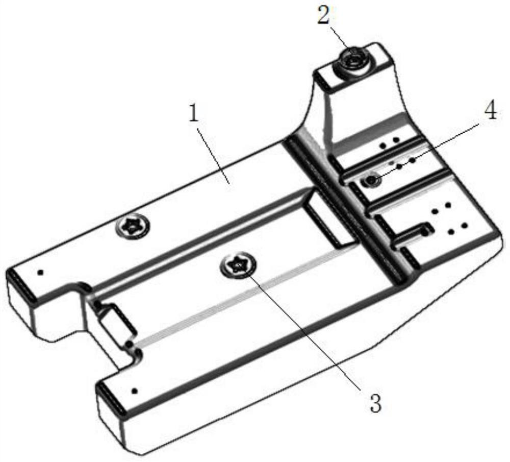
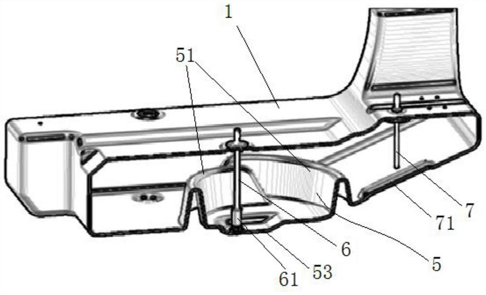
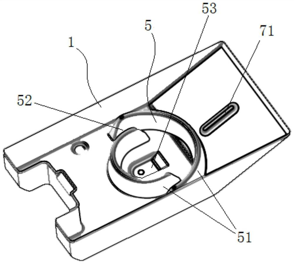
[0026] Such as figure 1 , 2 3. The rotomolded integrated oil tank with oil retaining structure shown in 3 includes a fuel tank body 1 on which an oil inlet 2, an oil suction port 3 and an oil return port 4 are arranged; an oil retaining structure 5 is arranged in the tank , the oil retaining structure 5 has two facing protrusions 51 surrounding the oil suction pipe 6, the two facing protrusions 51 surround the oil suction pipe 6 to form an oil suction area, and between the two protrusions 51 An oil inlet passage 52 is set, and the protruding part 51 is a circular arc protruding from the bottom of the fuel tank after installation to the top of the fuel tank. The two ends of the arc protrusion are located in another arc protrusion, and the gap between the overlapping parts of the two arc protrusions constitutes the oil inlet passage 52, wherein the arc of the large radius arc faces the oil return pipe 7, so that the oil inlet passage 52 is on the side away from oil return pipe...
Embodiment 2
[0031] As a further optimized design of Embodiment 1, the bottom plate of the oil storage box below the oil return pipe 7 is set as an inclined plate, and the inclination direction is inclined from the side of the oil return pipe to the side of the oil retaining mechanism, and on the bottom plate of the oil storage box at the outlet of the corresponding oil return pipe An oil receiving groove 71 is provided. This structure can ensure that the return oil is quickly dispersed and flows to the oil retaining structure, and the oil receiving groove 71 can not only enhance the strength of the box body, but also withstand the oil spray from the oil return pipe.
[0032] As a further optimized design of Embodiment 1, a settling groove 53 is set on the bottom plate of the oil tank in the two facing protrusions 51, the oil suction port of the oil suction pipe 6 is located above the settling groove 53, and at the oil suction port of the oil suction pipe 6 A filter layer 61 is installed. ...
Embodiment 3
[0035] As a different design of Embodiment 1, the raised piece 51 can also be designed as one or a combination of V-shaped and U-shaped, as long as the designed two raised pieces 51 have a certain height, they can form a circle around each other. The oil storage space only needs to have an oil inlet channel 52 .
[0036] The purpose of the foregoing embodiments is all to achieve the following technical effects:
[0037] 1. The oil enters the oil suction area from the oil inlet channel of the oil gear structure. The oil inlet channel can block the entry of large foreign matter, and the small particles of impurities that enter are deposited in the sedimentation groove. The oil suction port is placed above the sedimentation groove to ensure oil absorption and impurities. separation;
[0038] 2. The oil retaining structure prevents the oil entering the oil retaining structure from flowing out easily. When there is less oil in the fuel tank or the vehicle is tilted, there is oil a...
PUM
 Abstract
Description
Claims
Application Information
 - R&D Engineer
- R&D Manager
- IP Professional
- Industry Leading Data Capabilities
- Powerful AI technology
- Patent DNA Extraction
Browse by: Latest US Patents, China's latest patents, Technical Efficacy Thesaurus, Application Domain, Technology Topic, Popular Technical Reports.
© 2024 PatSnap. All rights reserved.Legal|Privacy policy|Modern Slavery Act Transparency Statement|Sitemap|About US| Contact US: help@patsnap.com