Sample-residue-free heat-insulating and reusable multifunctional cell counting and imaging device
A cell counting and multi-functional technology, applied in the direction of measuring devices, laboratory containers, instruments, etc., can solve the problems of loss of excitation intensity, low efficiency of the experimental process, energy loss of light on the flow channel plate, etc., to achieve convenient positioning, The effect of convenient material setting
- Summary
- Abstract
- Description
- Claims
- Application Information
AI Technical Summary
Problems solved by technology
Method used
Image
Examples
Embodiment 1
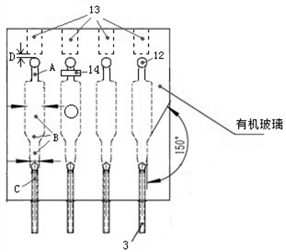
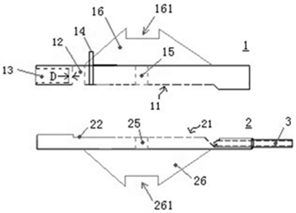
[0058] Such as figure 1 Shown is a top view of a four-microchannel heat-insulated reusable multifunctional cell counting imaging sample stage device of the present invention, including such as figure 2 As shown can cooperate with each other to form as figure 1 The first substrate 1 and the second substrate 2 of the shown four micro-channels, wherein the first substrate 1 and the second substrate 2 are made of plexiglass, respectively equipped with four micro-channels for forming the four micro-channels through the mutual cooperation. The first flow channel wall 11 and the second flow channel wall 21 of the flow channel, the first flow channel wall and the second flow channel wall have a transparent silica airgel layer, wherein each micro flow channel includes a microfluidic Valve section A, detection section B, discharge section C ( figure 1 ). The detection section B (500μm high) is composed of three sections of gradually narrowing flow channels, and the widest section is...
Embodiment 2
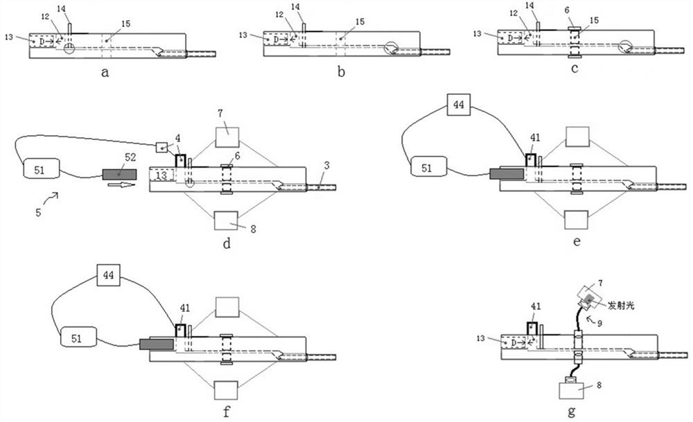
[0062] image 3 middle a is figure 2 The first substrate 1 and the second substrate 2 installed with the quartz drain tube 3 are combined to form a multifunctional cell counting imaging sample stage device by a thin layer of glass glue or double-sided adhesive. Wherein circled knife-type microfluidic valve 14 is open state, in image 3 The knife-type microfluidic valve 14 shown in b is in the closed state, and the sunken structure of the discharge section is circled, and the level of the sunken structure installed with the drain pipe 3 is shown. segment.
[0063] Such as image 3 As shown in c, on the four first optical interfaces 15 and the four second optical interfaces 25 corresponding to one of them, a threaded detachable plug 6 (that is, a bolt) is used to cooperate with the sealing ring to connect with the optical interface. The inner thread coupling screw-in method seals the widest section of the detection section B of the micro-channel to keep the valve in a close...
Embodiment 3
[0069] This embodiment is different from Embodiment 2 in that the first end of the first transparent cover 16 and the second transparent cover 26 are not installed, but the first ends of the two optical fiber light transmission accessories 9 are used to seal and connect the first optical interface 15 and the second optical interface respectively. 25 (sealed in the same way as the detachable blocking member 6, and sealed with a sealing material). Such as image 3 The illuminating device 7 and the detector 8 shown in middle g are respectively connected to the second ends of the respective optical fiber light-conducting fittings 9, so that the illumination light emitted by the illuminating device 7 passes through the optical fiber light-conducting fitting 9 and enters the inside of the micro-flow channel, while the transmitted light The second end of the optical fiber light transmission fitting 9 that is sealed and connected through the second optical interface 25 is imaged or re...
PUM
| Property | Measurement | Unit |
|---|---|---|
| thickness | aaaaa | aaaaa |
| thickness | aaaaa | aaaaa |
| thickness | aaaaa | aaaaa |
Abstract
Description
Claims
Application Information
 - R&D
- Intellectual Property
- Life Sciences
- Materials
- Tech Scout
- Unparalleled Data Quality
- Higher Quality Content
- 60% Fewer Hallucinations
Browse by: Latest US Patents, China's latest patents, Technical Efficacy Thesaurus, Application Domain, Technology Topic, Popular Technical Reports.
© 2025 PatSnap. All rights reserved.Legal|Privacy policy|Modern Slavery Act Transparency Statement|Sitemap|About US| Contact US: help@patsnap.com


